Table 9. current-sense configurations – Rainbow Electronics MAX1541 User Manual
Page 37
For high-power applications that do not require high-
accuracy current sensing or inductor-saturation protec-
tion, the MAX1540/MAX1541 can use the low-side
MOSFET’s on-resistance as the current-sense element
(R
SENSE
= R
DS(ON)
) by connecting CSN_ to the drain
of N
L_
and CSP_ to the source of N
L_
(Figure 14c). Use
the worst-case maximum value for R
DS(ON)
from the
MOSFET data sheet, and add some margin for the rise
in R
DS(ON)
with temperature. A good general rule is to
allow 0.5% additional resistance for each
°C of temper-
ature rise. Inductor-saturation protection must be dis-
abled with this configuration (LSAT = GND) since the
inductor current is only properly sensed when the low-
side MOSFET is turned on.
Alternatively, high-power applications that require
inductor saturation can constantly detect the inductor
current by connecting a series RC circuit across the
inductor (Figure 14d) with an equivalent time constant:
where R
L
is the inductor’s series DC resistance. In this
configuration, the current-sense resistance is equiva-
lent to the inductor’s DC resistance (R
SENSE
= R
L
). Use
the worst-case inductance and R
L
values provided by
the inductor manufacturer, adding some margin for the
inductance drop over temperature and load.
In all cases, ensure an acceptable valley current-limit
threshold voltage and inductor-saturation configura-
tions despite inaccuracies in sense-resistance values.
Output Capacitor Selection
The output filter capacitor must have low enough equiv-
alent series resistance (ESR) to meet output ripple and
load-transient requirements, yet have high enough ESR
to satisfy stability requirements.
For processor-core voltage converters and other appli-
cations where the output is subject to violent load tran-
sients, the output capacitor’s size depends on how
much ESR is needed to prevent the output from dipping
too low under a load transient. Ignoring the sag due to
finite capacitance:
In applications without large and fast load transients,
the output capacitor’s size often depends on how much
ESR is needed to maintain an acceptable level of out-
put voltage ripple. The output ripple voltage of a step-
down controller equals the total inductor ripple current
multiplied by the output capacitor’s ESR. Therefore, the
maximum ESR required to meet ripple specifications is:
The actual capacitance value required relates to the
physical size needed to achieve low ESR, as well as to
the chemistry of the capacitor technology. Thus, the
capacitor is usually selected by ESR and voltage rating
rather than by capacitance value (this is true of tanta-
lums, OS-CONs, polymers, and other electrolytics).
When using low-capacity filter capacitors, such as
ceramic capacitors, size is usually determined by the
capacity needed to prevent V
SAG
and V
SOAR
from
causing problems during load transients. Generally,
once enough capacitance is added to meet the over-
shoot requirement, undershoot at the rising load edge
is no longer a problem (see the V
SAG
and V
SOAR
equa-
tions in the Transient Response section). However, low-
capacity filter capacitors typically have high-ESR zeros
that may affect the overall stability (see the Output-
Capacitor Stability Considerations section).
R
V
I
LIR
ESR
RIPPLE
LOAD(MAX)
≤
×
∆
R
V
I
ESR
STEP
LOAD(MAX)
≤
∆
L
R
= C
R
L
EQ
EQ
×
MAX1540/MAX1541
Dual Step-Down Controllers with Saturation
Protection, Dynamic Output, and Linear Regulator
______________________________________________________________________________________
37
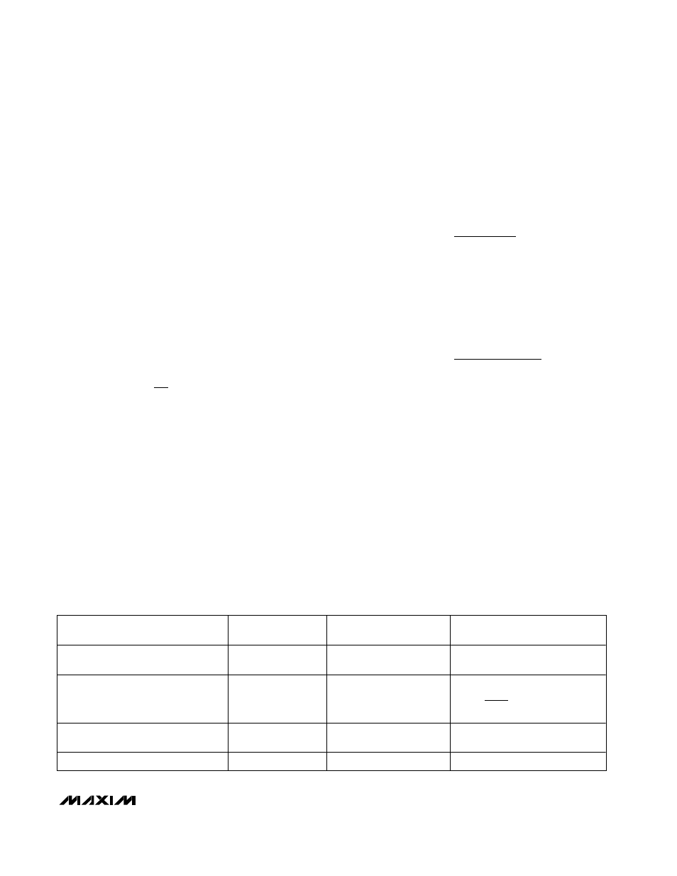
Table 9. Current-Sense Configurations
METHOD
CURRENT-SENSE
ACCURACY
INDUCTOR-SATURATION
PROTECTION
CURRENT-SENSE POWER LOSS
(EFFICIENCY)
a) Output current-sense resistor
High
Allowed
(highest accuracy)
R
SENSE
x I
OUT
2
b) Low-side current-sense resistor
High
Not allowed
(LSAT = GND)
c) Low-side MOSFET on-resistance
Low
Not allowed
(LSAT = GND)
No additional loss
d) Equivalent inductor DC resistance
Low
Allowed
No additional loss
1-
OUT
IN
SENSE
OUT
2
V
V
R
I
Ч
Ч