Pin description (continued) – Rainbow Electronics MAX1541 User Manual
Page 18
MAX1540/MAX1541
Dual Step-Down Controllers with Saturation
Protection, Dynamic Output, and Linear Regulator
18
______________________________________________________________________________________
PIN
MAX1540
MAX1541
NAME
FUNCTION
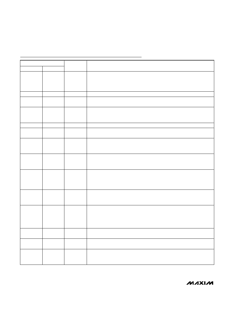
13
17
PGOOD2
Open-Drain Power-Good Output. PGOOD2 is low when the output voltage is more
than 10% (typ) above or below the normal regulation point, during soft-start, and in
shutdown. After the soft-start circuit has terminated, PGOOD2 becomes high
impedance if the output is in regulation.
14
18
DH2
High-Side Gate-Driver Output for Controller 2. DH2 swings from LX2 to BST2.
15
19
LX2
Inductor Connection for Controller 2. Connect to the switched side of the inductor.
LX2 serves as the lower supply rail for the DH2 high-side gate driver.
16
20
BST2
Boost Flying-Capacitor Connection for Controller 2. Connect to an external capacitor
and diode as shown in Figure 8. An optional resistor in series with BST2 allows the
DH2 pullup current to be adjusted.
17
21
GND
Analog and Power Ground. Connect backside pad to GND.
18
22
DL2
Low-Side Gate-Driver Output for Controller 2. DL2 swings from GND to LDOOUT
(MAX1540) or GND to V
DD
(MAX1541).
19
23
V+
Battery Voltage Input. The controller uses V+ to set the on-time one-shot timing. The
DH on-time is inversely proportional to input voltage over a range of 2V to 28V. For
the MAX1540, V+ also serves as the linear-regulator input supply.
—
24
LDOIN
Internal Linear-Regulator Input Supply. Connect to V+ or a voltage source from 4.5V
to 28V through a 1
Ω resistor. Bypass LDOIN to GND with a 4.7µF or greater
capacitor. For the MAX1540, LDOIN is internally connected to V+.
—
25
V
DD
MAX1541 Supply Voltage Input for the DL_ Gate Driver. Connect to the system
supply voltage (+4.5V to +5.5V). Bypass V
DD
to power ground with a 1µF or greater
ceramic capacitor. For the MAX1540, LDOOUT supplies the DL_ gate drivers
(V
DD
= LDOOUT).
20
26
LDOOUT
Linear Regulator Output. Bypass LDOOUT with a 1µF or greater capacitor per 5mA of
load (internal and external), with a minimum of 4.7µF. For the MAX1540, LDOOUT
powers the DL_ gate drivers (V
DD
internally connected to LDOOUT).
—
27
FBLDO
Feedback Input for the Linear Regulator. Connect to GND for a fixed 5V output. For
an adjustable output (1.25V to V
LDOIN
- 0.6V), connect FBLDO to a resistive voltage-
divider from LDOOUT to analog ground (GND). The FBLDO regulation voltage is
+1.25V. For the MAX1540, FBLDO is internally connected to GND for a fixed 5V
output.
21
28
DL1
Low-Side Gate-Driver Output for Controller 1. DL1 swings from GND to LDOOUT
(MAX1540) or GND to V
DD
(MAX1541).
22
29
LDOON
Linear-Regulator Enable Input. For automatic startup, connect to V+ or LDOIN
(MAX1541). Connect to GND to shut down the linear regulator.
23
30
BST1
Boost Flying-Capacitor Connection for Controller 1. Connect to an external capacitor
and diode as shown in Figure 8. An optional resistor in series with BST1 allows the
DH1 pullup current to be adjusted.
Pin Description (continued)