Chip information, Package information – Rainbow Electronics MAX863 User Manual
Page 16
MAX863
Dual, High-Efficiency, PFM, Step-Up
DC-DC Controller
16
______________________________________________________________________________________
___________________Chip Information
TRANSISTOR COUNT: 858
SUBSTRATE CONNECTED TO GND
Step-Up/Down SEPIC Converter
and 12V Supply
The circuit in Figure 9 provides a buck/boost function for
applications where the input voltage range can be
greater than or less than V
OUT1
. It provides 3.3V (up to
600mA) or 5V, as well as 12V (up to 200mA at V
IN
= 2.4V)
for powering flash memory or analog functions.
The main output employs a SEPIC topology using a
coupled inductor and a capacitor to transfer energy to
the output. C2 must be a low-ESR type capable of
withstanding high ripple current. Ceramic and Sanyo
OS-CONs work well, but low-ESR aluminum electrolyt-
ics (which are less costly) are tolerable. Do not use a
tantalum capacitor for C2. C2’s voltage rating must be
higher than the maximum input voltage. The MOSFET
must withstand a voltage equal to the sum of the input
and output voltages; i.e., when converting 11V to 3.3V,
the MOSFET must withstand 14.3V. The dual Schottky
diode D3 bootstraps power to the MAX863, allowing
use of the low-voltage start-up oscillator, as well as
improved gate-drive voltages during normal operation.
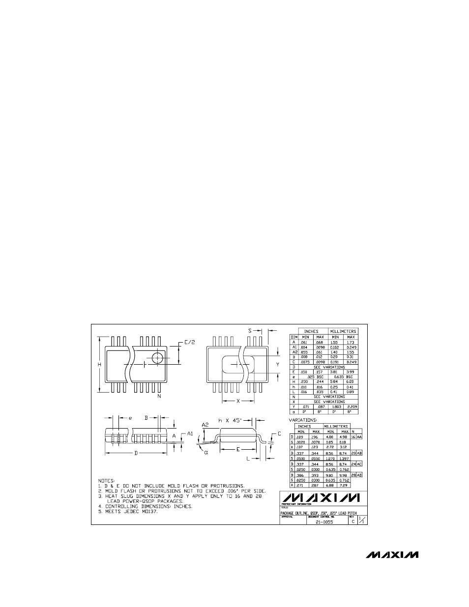
________________________________________________________Package Information
QSOP.EPS