Design procedure, Shutdown mode, Specify design objectives – Rainbow Electronics MAX863 User Manual
Page 10: For normal operation
MAX863
Dual, High-Efficiency, PFM, Step-Up
DC-DC Controller
10
______________________________________________________________________________________
Shutdown Mode
The MAX863 has two shutdown inputs useful for con-
serving power and extending battery life. Driving
SHDN1 or SHDN2 low turns off the corresponding DC-
DC controller and reduces quiescent current. Driving
both shutdown pins low turns off the reference, control,
and biasing circuitry, putting the MAX863 in a 1µA
shutdown mode. Connect SHDN1 and SHDN2 to V
DD
for normal operation.
__________________Design Procedure
Boost DC-DC converters using the MAX863 can be
designed in a few simple steps to yield a working first-
iteration design. All designs should be prototyped and
tested prior to production. Table 1 provides a list of
component suppliers.
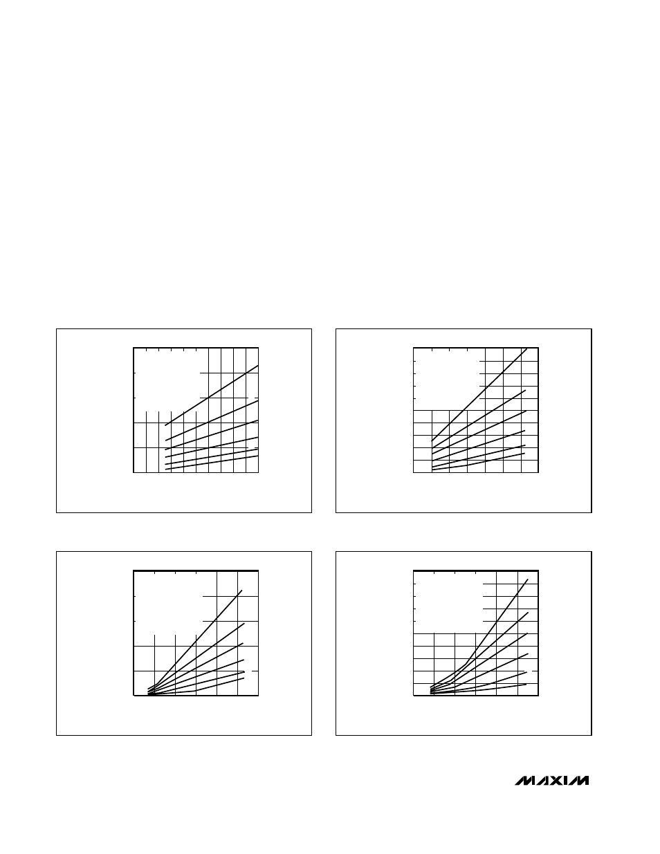
Two design methods are included. The first uses
graphs for selecting the peak current required for 3.3V,
5V, 12V, and 24V outputs. The second uses equations
for selecting the peak current and inductor value in cir-
cuits with other outputs. When designing high-voltage,
flyback, SEPIC, and autotransformer boost circuits,
contact Maxim’s Applications Department for the
appropriate design equations.
Specify Design Objectives
For each of the two outputs, specify the output voltage
and maximum load current, as well as maximum and
0
0.1
0
12
0.2
0.3
1.0
MAX863 FIG05D
INPUT VOLTAGE (V)
MAXIMUM OUTPUT CURRENT (A)
0.6
0.7
0.4
0.5
8
0.8
0.9
10
2
4
6
Cond: Single +5V
Code = FFFhex
V
OUT
= 24V, L = 1.5 L
MIN
A: I
PEAK
= 3A
B: I
PEAK
= 2A
C: I
PEAK
= 1.47A
D: I
PEAK
= 1A
E: I
PEAK
= 0.67A
F: I
PEAK
= 0.5A
A
B
C
D
E
F
Figure 5d. Maximum Output Current vs. Input Voltage and
IPEAK (V
OUT
= 24V)
0
1.0
4.5
0.4
0.6
0.2
2.0
MAX863 FIG05B
INPUT VOLTAGE (V)
MAXIMUM OUTPUT CURRENT (A)
1.2
1.4
0.8
1.0
3.5
1.6
1.8
4.0
2.5
1.5
2.0
3.0
Cond: Single +5V
Code = FFFhex
V
OUT
= 5V, L = 1.5 L
MIN
A: I
PEAK
= 3A
B: I
PEAK
= 2A
C: I
PEAK
= 1.47A
D: I
PEAK
= 1A
E: I
PEAK
= 0.67A
F: I
PEAK
= 0.5A
A
B
C
D
E
F
Figure 5b. Maximum Output Current vs. Input Voltage and
IPEAK (V
OUT
= 5V)
0
0
12
0.5
2.5
MAX863 FIG05C
INPUT VOLTAGE (V)
MAXIMUM OUTPUT CURRENT (A)
1.5
1.0
8
2.0
10
2
4
6
Cond: Single +5V
Code = FFFhex
V
OUT
= 12V, L = 1.5 L
MIN
A: I
PEAK
= 3A
B: I
PEAK
= 2A
C: I
PEAK
= 1.47A
D: I
PEAK
= 1A
E: I
PEAK
= 0.67A
F: I
PEAK
= 0.5A
A
B
C
D
E
F
Figure 5c. Maximum Output Current vs. Input Voltage and
IPEAK (V
OUT
= 12V)
0
1.0
3.0
0.5
2.5
MAX863 FIG05A
INPUT VOLTAGE (V)
MAXIMUM OUTPUT CURRENT (A)
2.0
1.5
1.0
1.4
2.4
2.0
2.6 2.8
1.8
1.2
1.6
2.2
Cond: Single +5V
Code = FFFhex
V
OUT
= 3.3V, L = 1.5 L
MIN
A: I
PEAK
= 3A
B: I
PEAK
= 2A
C: I
PEAK
= 1.47A
D: I
PEAK
= 1A
E: I
PEAK
= 0.67A
F: I
PEAK
= 0.5A
A
B
C
D
E
F
Figure 5a. Maximum Output Current vs. Input Voltage and
IPEAK (V
OUT
= 3.3V)