Applications information, Application circuits – Rainbow Electronics MAX863 User Manual
Page 15
MAX863
Dual, High-Efficiency, PFM, Step-Up
DC-DC Controller
______________________________________________________________________________________
15
MAX863
EXT2
CS2
V
OUT2
= 12V
FLYBACK OR SEPIC
OUTPUT
V
OUT1
= 3.3V, 600mA
V
IN
= 2.0V TO 11V OR V
OUT2
N1B
IRF7301
C7
0.1
µF
R4
115k
1%
C6
10pF
C2
1
µF
C5
100
µF
20V
≤0.1Ω
R2
50m
Ω
R3
1M
1%
N1A
R1
50m
Ω
R5
R6
R7
100k
C1
330
µF
10V
≤0.1Ω
D1
MBRS340T3
T1
10
µH, 2.5A
CTX10-4
D2
MBRS340T3
L2
10
µH
2A
C3
100
µF
10V
≤0.1Ω
C4
100
µF
10V
≤0.1Ω
C9
10
µF
ON/OFF
FB2
SHDN1
EXT1
D3
CMPSH-3C
CS1
LBI
LOW-BATTERY
DETECTOR OUTPUT
LBO
SENSE1 FB1
PGND
BOOT
V
DD
GND
SHDN2
REF
C8
82pF
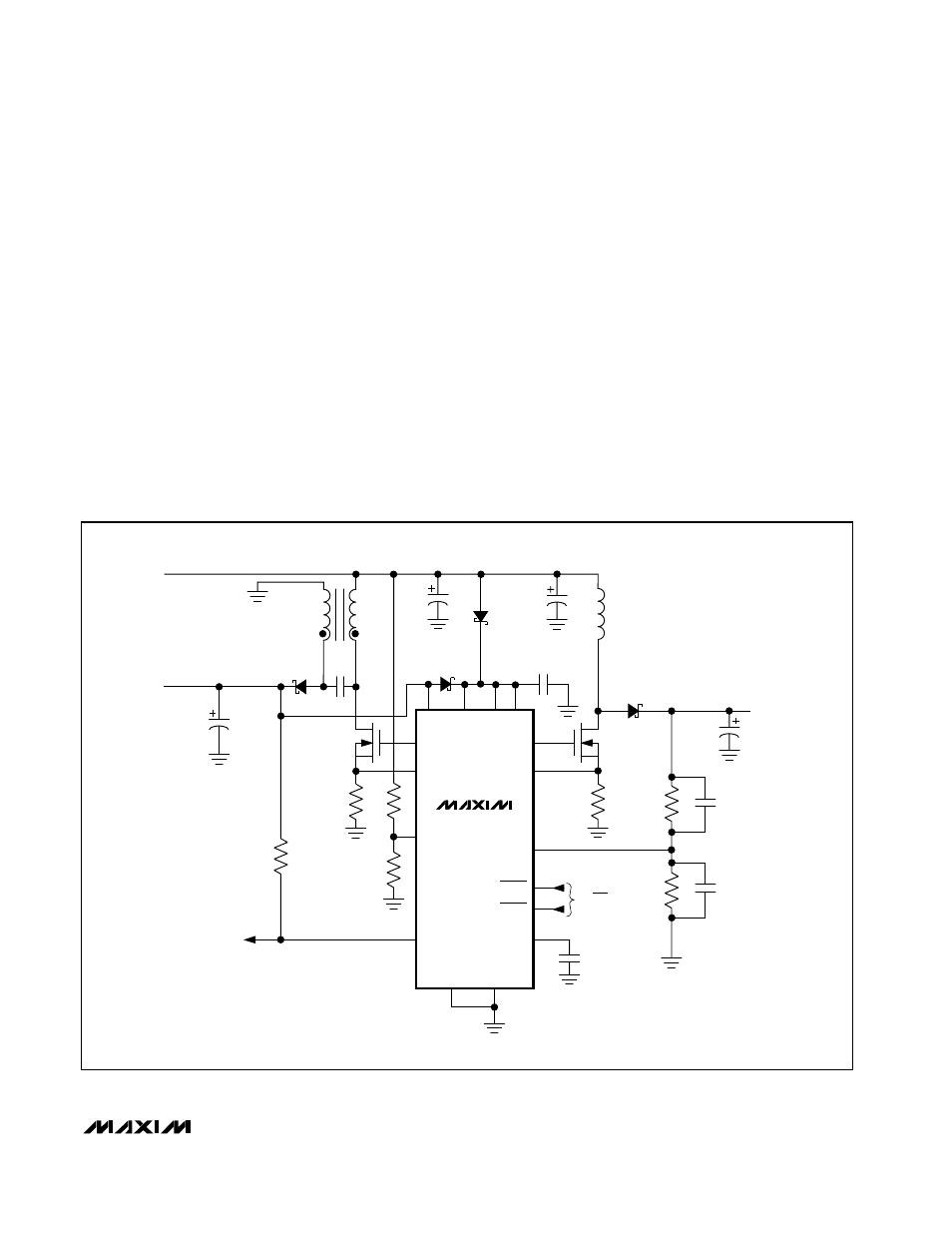
Figure 9. 3-Cell to 3.3V Step-Up/Step-Down Logic Supply with 12V for Flash Memory or Analog Functions
__________Applications Information
Low-Input-Voltage Operation
When the voltage at V
DD
falls and EXT1 or EXT2
approaches the MOSFET gate-to-source threshold volt-
age, the MOSFET may operate in its linear region and
dissipate excessive power. Prolonged operation in this
mode may damage the MOSFET if power dissipation
ratings are inadequate. This effect is more significant in
non-bootstrapped mode, but can occur in boot-
strapped mode if the input voltage drops so low that it
cannot support the load and causes the output voltage
to collapse. To avoid this condition, use logic-level or
low-threshold MOSFETs.
Starting Up Under Load
The Typical Operating Characteristics show the
Bootstrapped-Mode Minimum Start-Up Input Voltage
vs. Output Current graph. The MAX863 is not intended
to start up under full load in bootstrapped mode with
low input voltages.
________________Application Circuits
Bootstrapped 5V Logic and
24V LCD Bias Supply
The circuit in Figure 8 operates from two AA or AAA
cells, and generates 5V (up to 750mA) for logic and
24V (up to 35mA) for an LCD bias supply. OUT1 is
used to bootstrap the MAX863 for better MOSFET gate
drive. V
OUT1
can be set to 3.3V if low threshold
MOSFETs are used.