Table 1. component suppliers – Rainbow Electronics MAX863 User Manual
Page 13
MAX863
Dual, High-Efficiency, PFM, Step-Up
DC-DC Controller
______________________________________________________________________________________
13
Voltage ripple is the sum of contributions associated
with ESR and the capacitor value, as shown below:
V
RIPPLE
≅ V
RIPPLE,ESR
+ V
RIPPLE,C
To simplify selection, assume that 75% of the ripple
results from ESR and that 25% results from the capaci-
tor value. Voltage ripple as a consequence of ESR is
approximated by:
V
RIPPLE,ESR
≅ R
ESR
x I
PEAK
so:
Estimate input and output capacitor values for a given
voltage ripple as follows:
where V is the input or output voltage, depending on
which capacitor is being calculated.
Choose input capacitors with working voltage ratings
over the maximum input voltage, and output capacitors
with working voltage ratings higher than their respec-
tive outputs.
Add V
DD
and REF Bypass Capacitors
Bypass the MAX863 with 0.1µF or higher value ceramic
capacitors placed as close to the V
DD
, REF, and GND
pins as possible.
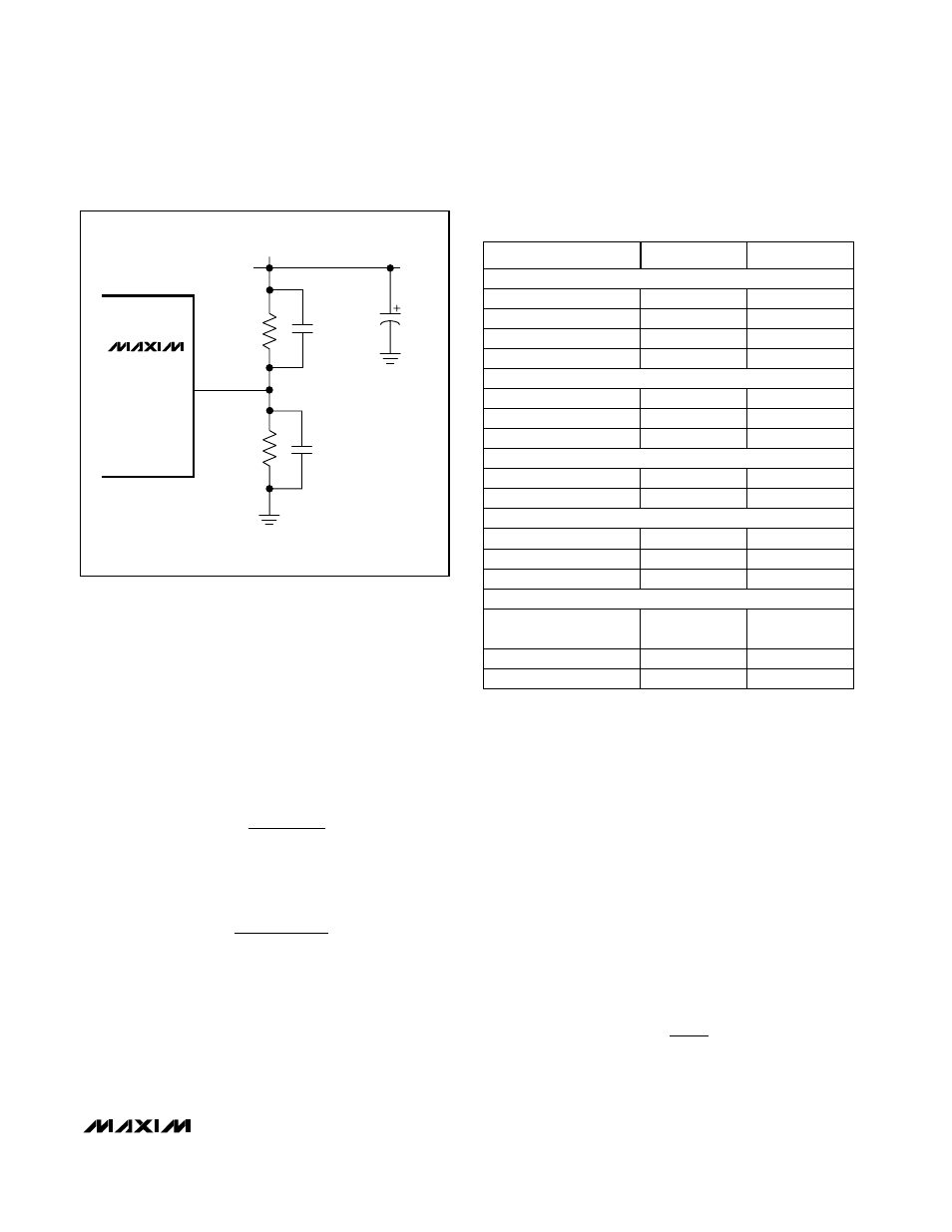
Set the Output Voltage
DC-DC converter 1 operates with a 3.3V, 5V, or
adjustable output. For a preset output, connect
SENSE1 to OUT1 (Figures 2 and 4a), then set FB1 to
V
DD
for 3.3V operation or to GND for 5V operation. For
an adjustable output, connect a resistor voltage divider
to the FB1 pin (Figure 7). In adjustable output circuits,
connect SENSE1 to GND.
DC-DC converter 2 can be adjusted from very high
voltages down to V
IN
using external resistors connect-
ed to the FB2 pin, as shown in Figure 7. Select feed-
back resistor R2 in the 10k
Ω to 500kΩ range. R1 is
given by:
where 1.25V is the voltage of the internal reference.
R1 = R2
V
1.25V
OUT
−
1
C
0.5L x I
V
x V
2
PEAK
RIPPLE,C
≥
R
V
I
ESR
RIPPLE,ESR
PEAK
≤
MAX863
FB1 OR FB2
C
OUT
C1
(OPTIONAL)
R1
R2
C2
(OPTIONAL FOR HIGH-
VOLTAGE CIRCUITS)
V
OUT1
OR V
OUT2
Figure 7. Adjustable Output Circuit
Table 1. Component Suppliers
PHONE
Inductors
SUPPLIER
Marcon/United
Chemi-Con
(847) 696-2000
TDK
(847) 390-4373
Vishay/Vitramon
(203) 268-6261
(847) 390-4428
(203) 452-5670
Large-Value Ceramic Capacitors
(847) 696-9278
Motorola
(602) 303-5454
AVX
(803) 946-0690
Sanyo USA
(619) 661-6835
Sprague
(603) 224-1961
(619) 661-1055
(603) 224-1430
Electrolytic Capacitors
(803) 626-3123
Dale/Vishay
(402) 564-3131
IRC
(512) 992-7900
(402) 563-6418
(512) 992-3377
(602) 994-6430
Current-Sense Resistors
Sumida USA
(847) 956-0666
Central Semiconductor
(516) 435-1110
International Rectifier
(310) 322-3331
(516) 435-1824
(310) 322-3232
(847) 956-0702
MOSFETs and Diodes
Coiltronics
(561) 241-7876
Dale Inductors
(605) 668-4131
(561) 241-9339
(605) 665-1627
FAX
(847) 639-1469
Coilcraft
(847) 639-6400