Applications information, Chip information, Typical application circuits – Rainbow Electronics MAX2389 User Manual
Page 9
IF Output Port
The mixer output appears on the differential IF+ and IF-
pins. These open-collector outputs require an external
inductor to V
CC
for DC biasing. This port typically
requires a matching network for coupling to an external
IF filter. Figures 1 and 2 show examples of differential
and single-ended IF port connections.
Applications Information
Layout
A properly designed PC board is essential to any
RF/microwave circuit. Keep RF signal lines as short as
possible to minimize losses and radiation. Always use
controlled impedance lines on all high-frequency inputs
and outputs and use low-inductance connections to
ground on all GND pins. At the mixer outputs, keep the
differential lines together and of the same length to
ensure signal balance.
For the best gain and noise performance, use high-
quality components for the LNA input matching circuit,
and solder the slug evenly to the board ground plane.
For the power supplies, a star topology works well to
isolate between different sections of the device. Each
V
CC
node has its own path to a central V
CC
. Place
decoupling capacitors that provide low impedance at
the RF frequency of interest close to all V
CC
connec-
tions. The central V
CC
should have a large decoupling
capacitor as well. (Use MAX2387/MAX2388/MAX2389
EV kit as an example.)
Chip Information
TRANSISTOR COUNT: 208
MAX2387/MAX2388/MAX2389
W-CDMA LNA/Mixer ICs
_______________________________________________________________________________________
9
12
BIAS_SET
11
GND
10
LNA_IN
Z
L
IF
SAW
9
V
CC
V
CC
V
CC
8
IF+
7
IF-
4
5
LO+
VCO
10k
Ω
24k
Ω
10k
Ω
10k
Ω
20
Ω
10nF
10
µF
82pF
2.2nH
2.2nH
27nH
27nH
10nF
82pF
22pF
39pF
39pF
6800pF
0.8pF
RX
TX
6800pF
0.8pF
6
LO-
1
LNA_OUT
2
GAIN
3
MIX_IN
SHDN
BIAS
MAX2387
MAX2388
MAX2389
RX BPF
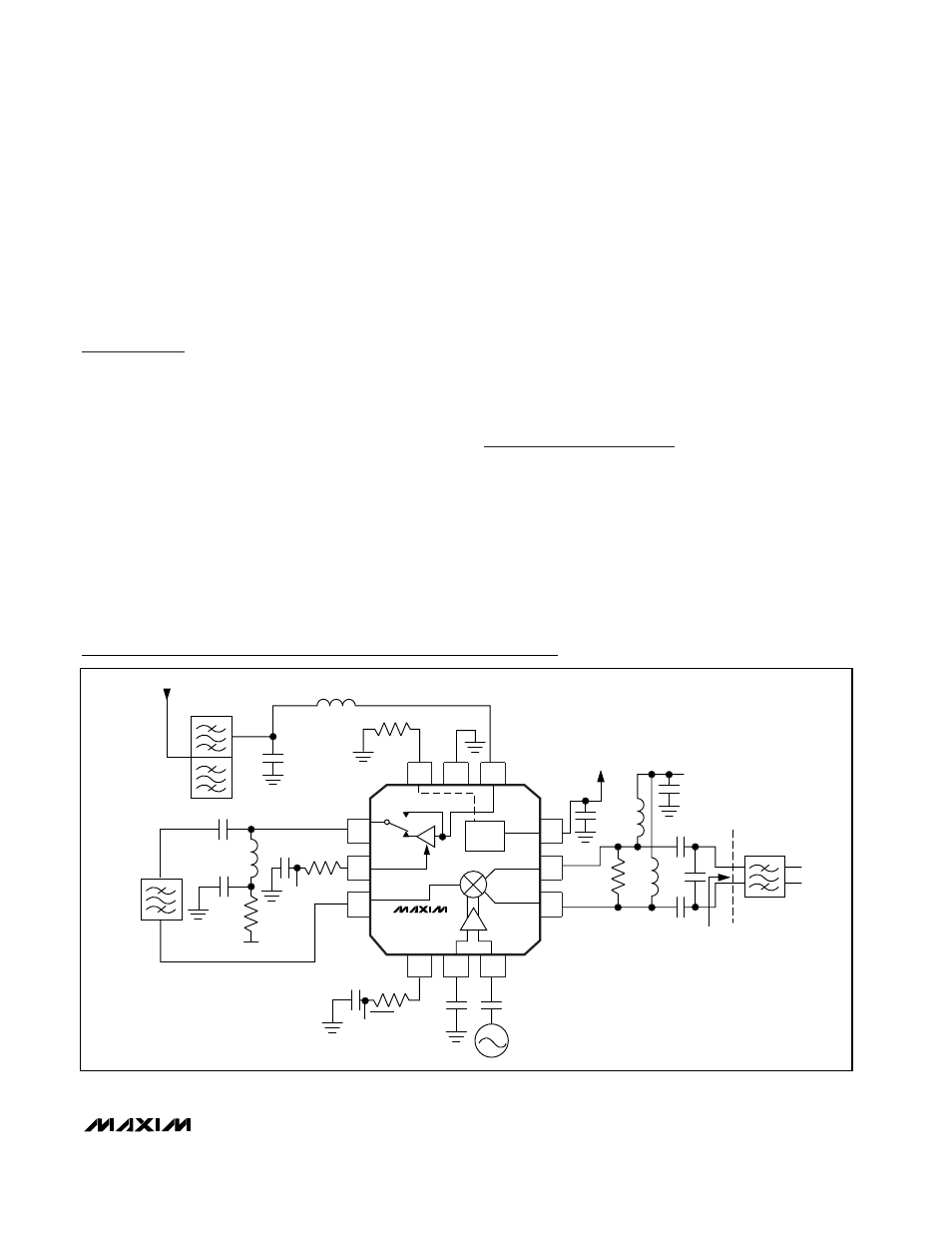
Figure 1. MAX2387/MAX2388/MAX2389 Differential IF Load; Single-Ended VCO
Typical Application Circuits