Functional description – Rainbow Electronics LM81 User Manual
Page 29
Functional Description
(Continued)
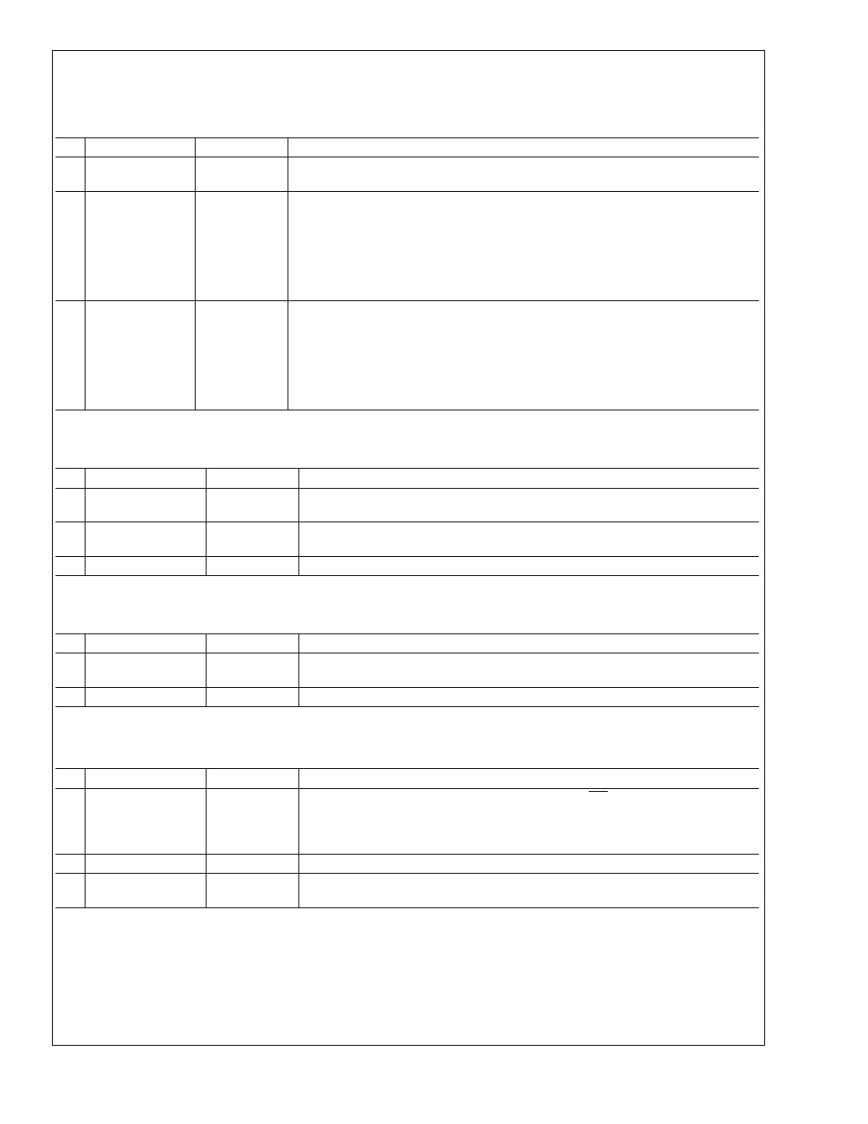
13.10 VID/Fan Divisor Register — Address 47h
Power on default –
<
7:4
>
is 0101, and
<
3:0
>
is mapped to VID
<
3:0
>
Bit
Name
Read/Write
Description
0-3
VID
<
3:0
>
Read Only
The VID
<
3:0
>
inputs from the Pentium/PRO power supplies that indicate the
operating voltage (e.g. 1.5V to 2.9V).
4-5
FAN1 RPM
Control
Read/Write
FAN1 Speed Control.
<
5:4
>
= 00 - divide by 1;
<
5:4
>
= 01 - divide by 2;
<
5:4
>
= 10 - divide by 4;
<
5:4
>
= 11 - divide by 8.
6-7
FAN2 RPM
Control
Read/Write
FAN2 Speed Control.
<
7:6
>
= 00 - divide by 1;
<
7:6
>
= 01 - divide by 2;
<
7:6
>
= 10 - divide by 4;
<
7:6
>
= 11 - divide by 8.
13.11 Serial Bus Address Register — Address 48h
Power on default – Serial Bus address
<
6:0
>
= 010 11(A1)(A0) and
<
7
>
= 0 binary
Bit
Name
Read/Write
Description
0-1
Serial Bus
Address
Read Only
Serial Bus address
<
1:0
>
= A1 A0
2-6
Serial Bus
Address
Read/Write
Serial Bus address
<
6:2
>
= 010 11
7
Reserved
Read/Write
13.12 VID4 Register — Address 49h
Power on default –
<
7:1
>
= 100 000,
<
0
>
= VID4.
Bit
Name
Read/Write
Description
0
VID4
Read Only
VID4 input from Pentium/PRO power supply that indicate the operating voltage of
the processor (e.g. 1.5V to 2.9V).
1-7
Reserved
Read/Write
13.13 Temperature Configuration Register — Address 4Bh
Power on default –
<
7:0
>
= 0000 0001 binary
Bit
Name
Read/Write
Description
0-1
Temperature
Interrupt Mode
Select Bits
Read/Write
The state of these bits select the interrupt mode for INT as described below.
<
1:0
>
= 00 or
<
1:0
>
= 11: Repetitive Interrupt Mode
<
1:0
>
= 01: One-Time Interrupt Mode
<
1:0
>
= 10: Comparator Mode
2-6
Reserved
Read/Write
7
Temperature
Resolution
Read Only
For 8-bit plus sign temperature resolution:
<
7
>
= LSB ( 0.5˚C)
LM81
www.national.com
29