Test circuit functional description – Rainbow Electronics LM81 User Manual
Page 10
Test Circuit
Functional Description
1.0 GENERAL DESCRIPTION
The LM81 provides 6 analog inputs, a temperature sensor, a
Delta-Sigma ADC (Analog-to-Digital Converter), a DAC out-
put, 2 fan speed counters, WATCHDOG registers, and a
variety of inputs and outputs on a single chip. A two wire
Serial Bus interface is included. The LM81 performs power
supply, temperature, fan control and fan monitoring for per-
sonal computers.
The analog inputs are useful for monitoring several power
supplies present in a typical computer. The LM81 includes
internal resistor dividers that scale and/or offset external
Vccp, +2.5V, +3.3V, +5.0V and +12V power supply voltages
to a 3/4 scale nominal ADC output. The LM81 ADC then
continuously converts the scaled inputs to 8-bit digital words.
Measurement of negative voltages (such as -5V and -12V
power supplies) can be accommodated with an external
resistor divider applied to the Vccp2 input. Temperature is
converted to a 9-bit or 12-bit two’s-complement digital word
with a 0.5˚C LSB or 0.0625˚C LSB, respectively.
Fan inputs measure the period of tachometer pulses from
the fans, providing a higher count for lower fan speeds. The
fan inputs are Schmitt-Trigger digital inputs with an accept-
able range of 0V to V
+
and a transition level of approximately
V
+
/2. Full scale fan counts are 255 (8-bit counter) and this
represents a stopped or very slow fan. Nominal speeds,
based on a count of 153, are programmable from 1100 to
8800 RPM on FAN1 and FAN2. Schmitt-Trigger input cir-
cuitry is included to accommodate slow rise and fall times. A
0V to 1.25V DAC output voltage range can be used for
control of fan speed.
The LM81 has several internal registers, as shown in
Figure
4, Table 1 and Section 13.0. These include:
•
Configuration Register:
Provides control and con-
figuration.
•
Interrupt Status Registers:
Two registers to provide
status of each WATCHDOG limit or Interrupt event.
•
Interrupt Mask Registers:
Allows masking of indi-
vidual Interrupt sources, as well as separate masking for
each of the two hardware Interrupt outputs.
•
CI Clear Register:
Allows transmitting a 20 ms low
pulse on the chassis intrusion pin (CI).
•
VID/Fan Divisor Register:
This register contains the
state of the VID0-VID3 input lines and the divisor bits for
FAN1 and FAN2 inputs.
•
Serial Bus Address Register:
Contains the Serial Bus
address. At power on it assumes the default value of
01011XX binary, and can be altered by the state of A0
and A1.
•
VID4 Register:
Contains the state of the VID4 input.
•
Temperature Configuration Register:
Selects the in-
terrupt mode and contains the 0.5˚C LSB of the tempera-
ture reading.
•
Extended Mode Registers:
Enable and control the
Extended Mode which includes the LSBs of the 12-bit
temperature reading, T_CRIT, and T
HYST
•
Value RAM:
The DAC digital input, monitoring results
(temperature, voltages, fan counts), WATCHDOG limits,
and Company/Stepping IDs are all contained in the Value
RAM. The Value RAM consists of a total of 34 bytes,
addresses 15h - 3Fh, containing:
— byte 1 at address 15h a manufacturers test register
— locations 16h - 18h are unassigned and do not have
associated registers
— byte 2 at address 19h contains the DAC Data Register
— locations 1Ah - 1Fh are unassigned and do not have
associated registers
— the next 10 bytes at addresses 20h -29h contain all of
the results, with address 26h reserved
— the next 18 bytes at addresses 2Bh-3Ch are the
WATCHDOG limits
— the last 2 bytes at addresses 3Eh and 3Fh contain the
Company ID and Stepping ID numbers, respectively
When the LM81 is started, it cycles through each measure-
ment in sequence, and it continuously loops through the
sequence approximately once every 400 ms. Each mea-
sured value is compared to values stored in WATCHDOG, or
Limit registers. When the measured value violates the pro-
grammed limit the LM81 will set a corresponding Interrupt in
the Interrupt Status Registers. The hardware Interrupt line
INT is fully programmable with separate masking of each
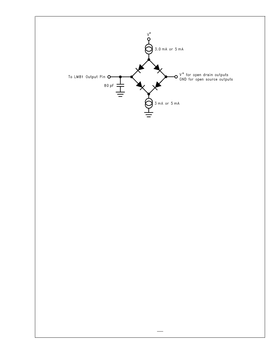
DS100072-6
FIGURE 3. Digital Output Load Test Circuitry
LM81
www.national.com
10