3v, t, 25°c – Rainbow Electronics MAX2641 User Manual
Page 7
MAX2640/MAX2641
400MHz to 2500MHz SiGe
Ultra-Low-Noise Amplifiers
_______________________________________________________________________________________
7
Layout and Power-Supply Bypassing
A properly designed PC board is essential to any
RF/microwave circuit. Be sure to use controlled imped-
ance lines on all high-frequency inputs and outputs.
The power supply should be bypassed with decoupling
capacitors located close to the device V
CC
pins. For
long V
CC
lines, it may be necessary to add additional
decoupling capacitors. These additional capacitors
can be located further away from the device package.
Proper grounding of the GND pins is essential. If the
PC board uses a topside RF ground, connect it directly
to all GND pins. For a board where the ground plane is
not on the component side, the best technique is to
connect the GND pin to the board with a plated
through-hole close to the package.
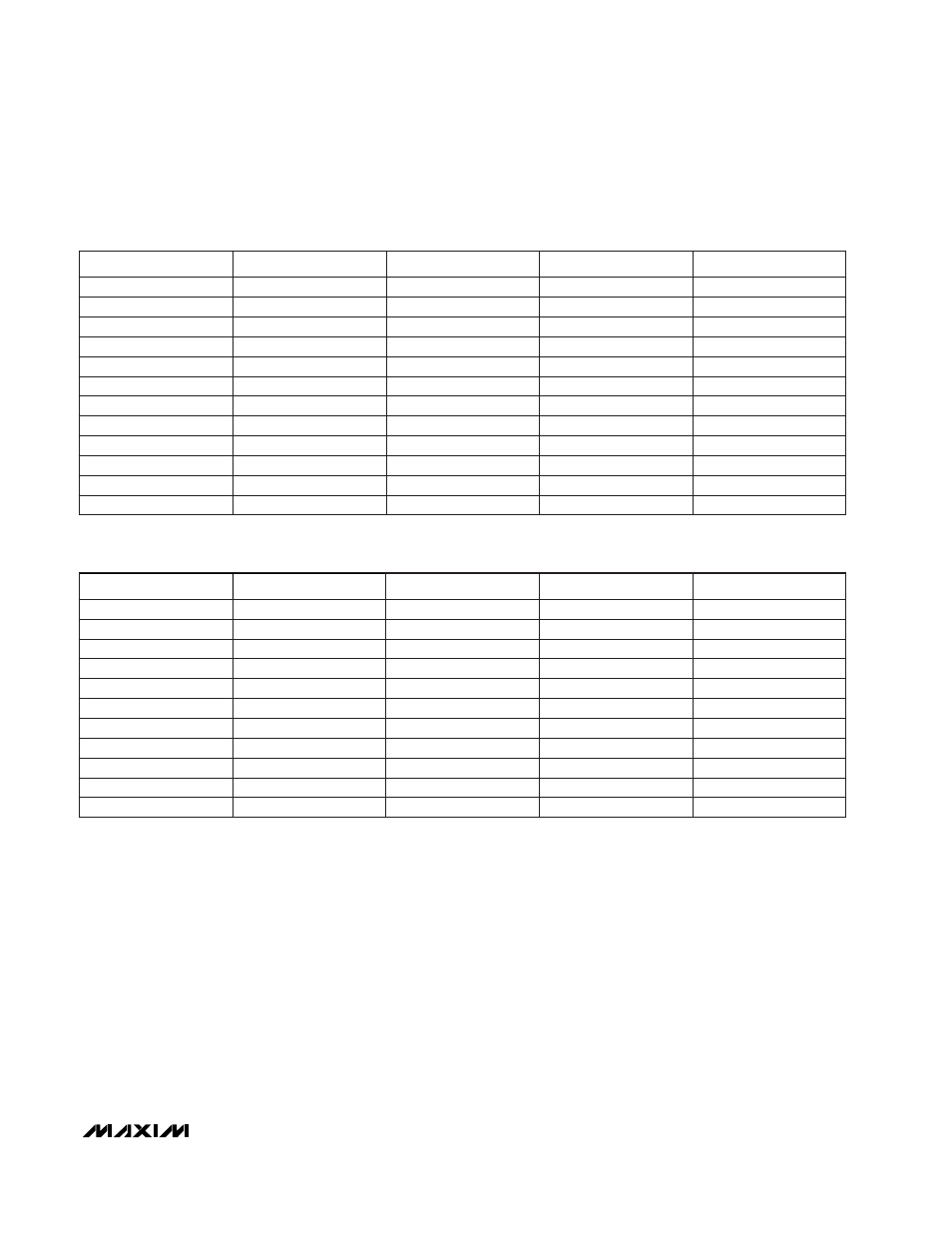
FREQUENCY (MHz)
f
MIN
(dB)
Γ
opt
Γ
opt
ANGLE
R
N
(
Ω
)
1500
1.02
0.43
44
12.4
1600
1.05
0.40
47
11.8
1700
1.08
0.38
50
11.3
1800
1.10
0.36
54
10.8
1900
1.14
0.32
58
10.3
2000
1.17
0.30
62
9.9
2100
1.20
0.28
66
9.4
2200
1.23
0.25
71
9.0
2300
1.27
0.22
77
8.6
2400
1.30
0.19
82
8.3
2500
1.34
0.17
91
8.0
Table 3. MAX2640 Typical Noise Parameters at V
CC
= +3V, T
A
= +25°C
Table 4. MAX2641 Typical Noise Parameters at V
CC
= +3V, T
A
= +25°C
7.0
84
0.26
1.06
1500
7.4
77
0.29
1.01
1400
7.9
68
0.32
0.97
1300
8.3
62
0.35
0.93
1200
8.8
56
0.37
0.89
1100
9.3
50
0.40
0.85
1000
9.7
45
0.43
0.82
900
10.2
40
0.46
0.78
800
10.8
35
0.48
0.75
700
11.3
30
0.51
0.72
600
11.9
25
0.54
0.69
500
12.5
21
0.56
0.66
400
R
N
(
Ω
)
Γ
opt
ANGLE
Γ
opt
f
MIN
(dB)
FREQUENCY (MHz)