Rainbow Electronics MAX2641 User Manual
General description, Applications, Features
For free samples & the latest literature: http://www.maxim-ic.com, or phone 1-800-998-8800.
For small orders, phone 1-800-835-8769.
General Description
The MAX2640/MAX2641 are low-cost, ultra-low-noise
amplifiers designed for applications in the cellular, PCS,
GPS, and 2.4GHz ISM frequency bands. Operating from
a single +2.7V to +5.5V supply, these devices consume
only 3.5mA of current while providing a low noise fig-
ure, high gain, high input IP3, and an operating fre-
quency range that extends from 400MHz to 2500MHz.
The MAX2640 is optimized for 400MHz to 1500MHz
applications, with a typical performance of 15.1dB gain,
input IP3 of -10dBm, and a noise figure of 0.9dB at
900MHz. The MAX2641 is optimized for 1400MHz to
2500MHz applications, with a typical performance of
14.4dB gain, an input IP3 of -4dBm, and a noise figure
of 1.3dB at 1900MHz.
These devices are internally biased, eliminating the
need for external bias resistors and chokes. In a typical
application, the only external components needed are a
two-element input match, input and output blocking
capacitors, and a V
CC
bypass capacitor.
The MAX2640/MAX2641 are designed on a high-fre-
quency, low-noise, advanced silicon-germanium
process and are offered in the space-saving 6-pin
SOT23 package.
Applications
400MHz/900MHz/2.4GHz ISM Radios
Cellular/PCS Handsets
GPS Receivers
Cordless Phones
Wireless LANs
Wireless Data
Features
♦
Wide Operating Frequency Range
MAX2640: 400MHz to 1500MHz
MAX2641: 1400MHz to 2500MHz
♦
Low Noise Figure
MAX2640: 0.9dB at 900MHz
MAX2641: 1.2dB at 1575MHz
1.3dB at 1900MHz
1.5dB at 2450MHz
♦
High Gain
MAX2640: 15.1dB at 900MHz
MAX2641: 15.7dB at 1575MHz
14.4dB at 1900MHz
13.5dB at 2450MHz
♦
High Reverse Isolation
MAX2640: 40dB at 900MHz
MAX2641: 31dB at 1575MHz
30dB at 1900MHz
24dB at 2450MHz
♦
+2.7V to +5.5V Single-Supply Operation
♦
Low 3.5mA Supply Current
♦
Ultra-Small SOT23-6 Package
MAX2640/MAX2641
400MHz to 2500MHz SiGe
Ultra-Low-Noise Amplifiers
________________________________________________________________
Maxim Integrated Products
1
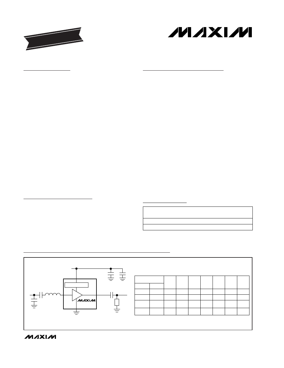
C3
C4
Z1
RFIN
C1
V
CC
V
CC
RFIN
C2
Z
M1
BIAS GENERATOR
GND
LNA
RF OUT
RF OUT
MAX2640/1
Z
M2
*The series inductor Z1 can be replaced by a transmission line of appropriate impedance
and electrical length.
FREQUENCY (MHz)
C1
VALUE
(pF)
C2
VALUE
(pF)
C3
VALUE
(pF)
C4
VALUE
(pF)
Z1*
VALUE
(nH)
ZM1
VALUE
(pF)
ZM2
VALUE
MAX2640 MAX2641
900
—
—
—
—
1575
1900
2450
470
100
470
470
3
100
100
100
470
470
470
470
—
—
—
100
9.85
5.6
2.55
1.65
2
1
1
1
—
6.8nH
1pF
1pF
Typical Operating Circuits
19-1384; Rev 1; 2/99
PART
MAX2640
EUT-T
MAX2641
EUT-T
-40°C to +85°C
-40°C to +85°C
TEMP.
RANGE
PIN-
PACKAGE
6 SOT23-6
6 SOT23-6
EVALUATION KIT
FOLLOWS DATA SHEET
Ordering Information
SOT
TOP MARK
AAAV
AAAW
Pin Configuration appears at end of data sheet.