Typical operating characteristics, Rf electrical characteristics (continued) – Rainbow Electronics MAX2641 User Manual
Page 3
MAX2640/MAX2641
400MHz to 2500MHz SiGe
Ultra-Low-Noise Amplifiers
_______________________________________________________________________________________
3
Note 2:
Guaranteed by design and characterization.
Note 3:
Measured using typical operating circuit. Input and output impedance matching networks were optimized for best simulta-
neous gain and noise-figure performance.
Note 4:
External component and circuit losses degrade noise-figure performance. Specification excludes external component and
circuit board losses.
Note 5:
Measured with two input tones, f
1
= 899MHz, f
2
= 901MHz, both at -34dBm per tone.
Note 6:
Measured with two input tones, f
1
= 1899MHz, f
2
= 1901MHz, both at -34dBm per tone.
Note 7:
Measured with two input tones, f
1
= 1574MHz, f
2
= 1576MHz, both at -34dBm per tone.
Note 8:
Measured with two input tones, f
1
= 2449MHz, f
2
= 2451MHz, both at -34dBm per tone.
RF ELECTRICAL CHARACTERISTICS (continued)
(V
CC
= +3.0V, P
RFIN
= -34dBm, Z
O
= 50
Ω
, T
A
= +25°C, unless otherwise noted.) (Notes 2 and 3)
(Note 7)
(Note 4)
CONDITIONS
dBm
+1.4
Input Third-Order Intercept Point
dBm
-21
Input 1dB Gain Compression Point
dB
-31
Reverse Isolation
dB
15.7
Gain
dB
1.2
Noise Figure
dB
-8
Input Return Loss
dB
-15
Output Return Loss
UNITS
MIN
TYP
MAX
PARAMETER
(Note 8)
(Note 4)
dBm
-2.5
Input Third-Order Intercept Point
dBm
-19
Input 1dB Gain Compression Point
dB
-24
Reverse Isolation
dB
13.5
Gain
dB
1.5
Noise Figure
dB
-10
Input Return Loss
dB
-11
Output Return Loss
MAX2641 (f
RFIN
= 1575MHz)
MAX2641 (f
RFIN
= 2450MHz)
0
2
1
4
3
5
6
2
4
3
5
6
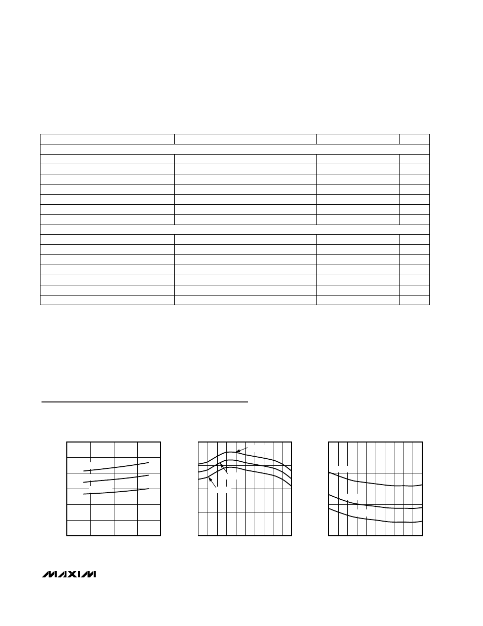
MAX2640
SUPPLY CURRENT vs. SUPPLY VOLTAGE
MAX2640-01
V
CC
(V)
I
CC
(mA)
T
A
= +85°C
T
A
= +25°C
T
A
= -40°C
12
13
15
14
16
800
840
880
920
960
1000
MAX2640 MATCHED AT 900MHz
GAIN vs. FREQUENCY
MAX2640-01
FREQUENCY (MHz)
GAIN (dB)
T
A
= -40°C
T
A
= +25°C
T
A
= +85°C
0
1
2
3
800
880
840
920
960
1000
MAX2640 MATCHED AT 900MHz
NOISE FIGURE vs. FREQUENCY
MAX2640-03
FREQUENCY (MHz)
NOISE FIGURE (dB)
T
A
= +85°C
T
A
= +25°C
T
A
= -40°C
Typical Operating Characteristics
(V
CC
= +3V, P
RFIN
= -34dBm, Typical Operating Circuits, T
A
= +25°C, unless otherwise noted.)