Rainbow Electronics MAX920 User Manual
Page 11
MAX917–MAX920
SOT23, 1.8V, Nanopower, Beyond-the-Rails
Comparators With/Without Reference
______________________________________________________________________________________
11
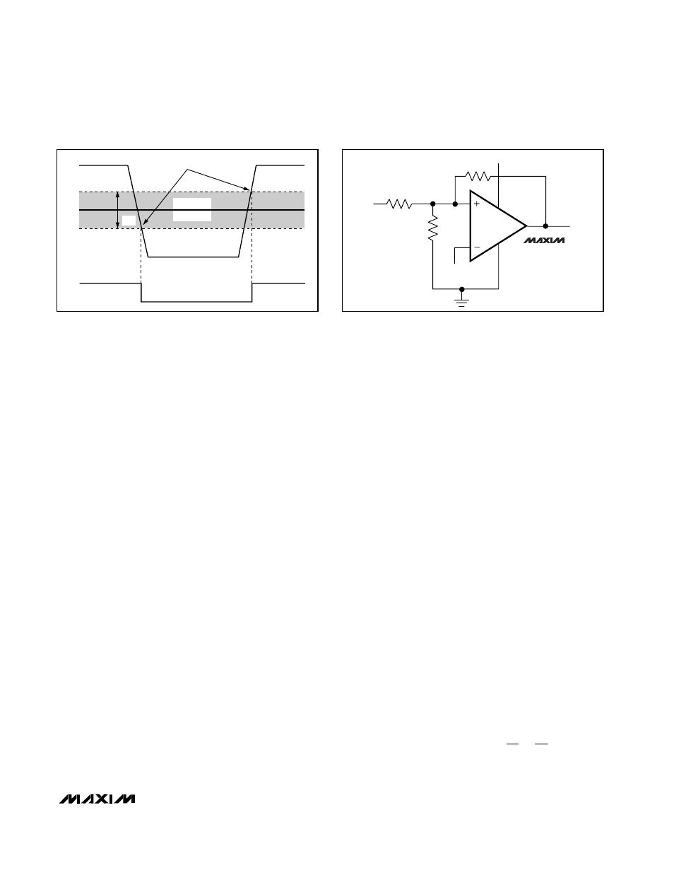
THRESHOLDS
OUT
IN+
IN-
V
HB
HYSTERESIS
BAND
V
THF
V
THR
Figure 2. Threshold Hysteresis Band
V
CC
MAX917
MAX919
OUT
R3
R1
R2
V
REF
V
EE
V
IN
V
CC
Figure 3. MAX917/MAX919 Additional Hysteresis
Additional Hysteresis (MAX917/MAX919)
The MAX917/MAX919 have a 4mV internal hysteresis
band (V
HB
). Additional hysteresis can be generated
with three resistors using positive feedback (Figure 3).
Unfortunately, this method also slows hysteresis re-
sponse time. Use the following procedure to calculate
resistor values.
1) Select R3. Leakage current at IN is under 2nA, so
the current through R3 should be at least 0.2µA to
minimize errors caused by leakage current. The cur-
rent through R3 at the trip point is (V
REF
- V
OUT
)/R3.
Considering the two possible output states in solving
for R3 yields two formulas: R3 = V
REF
/I
R3
or R3 =
(V
CC
- V
REF
)/I
R3
. Use the smaller of the two resulting
resistor values. For example, when using the
MAX917 (V
REF
= 1.245V) and V
CC
= 5V, and if we
choose I
R3
= 1µA, then the two resistor values are
1.2M
Ω
and 3.8M
Ω
. Choose a 1.2M
Ω
standard value
for R3.
2) Choose the hysteresis band required (V
HB
). For this
example, choose 50mV.
3) Calculate R1 according to the following equation:
R1 = R3 (V
HB
/ V
CC
)
For this example, insert the values
R1 = 1.2M
Ω
(50mV/5V) = 12k
Ω
4) Choose the trip point for V
IN
rising (V
THR
) such that
V
THR
> V
REF
·
(R1 + R3)/R3 (V
THF
is the trip point for
V
IN
falling). This is the threshold voltage at which the
comparator switches its output from low to high as
V
IN
rises above the trip point. For this example,
choose 3V.
5) Calculate R2 as follows:
R2 = 1/[V
THR
/(V
REF
·
R1) - (1 / R1) - (1 / R3)]
R2 = 1/[3.0V/(1.2V
·
12k
Ω
) - (1 / 12k
Ω
) -
(1/1.2M
Ω
)] = 8.05k
Ω
For this example, choose an 8.2k
Ω
standard value.
6) Verify the trip voltages and hysteresis as follows:
V
IN
rising: V
THR
= V
REF
·
R1 [(1 / R1) + (1 / R2)
+ (1 / R3)]
V
IN
falling: V
THF
= V
THR
- (R1
·
V
CC
/ R3)
Hysteresis = V
THR
- V
THF
Additional Hysteresis (MAX918/MAX920)
The MAX918/MAX920 have a 4mV internal hysteresis
band. They have open-drain outputs and require an
external pull-up resistor (Figure 4). Additional hystere-
sis can be generated using positive feedback, but the
formulas differ slightly from those of the MAX917/
MAX919. Use the following procedure to calculate
resistor values.
1) Select R3 according to the formulas R3 = V
REF
/ 1µA
or R3 = (V
CC
- V
REF
)/1µA - R4. Use the smaller of
the two resulting resistor values.
2) Choose the hysteresis band required (V
HB
).
3) Calculate R1 according to the following equation:
R1 = (R3 + R4) (V
HB
/V
CC
)
4) Choose the trip point for V
IN
rising (V
THR
) (V
THF
is
the trip point for V
IN
falling). This is the threshold
voltage at which the comparator switches its output
from low to high as V
IN
rises above the trip point.
5) Calculate R2 as follows:
R2
1/ V
/ V
R1
1
R1
1
R3
THR
REF
=
(
)
−
−
⋅