Applications information – Rainbow Electronics MAX920 User Manual
Page 10
Output Stage Circuitry
The MAX917–MAX920 contain a unique break-before-
make output stage capable of rail-to-rail operation with
up to ±8mA loads. Many comparators consume orders
of magnitude more current during switching than dur-
ing steady-state operation. However, with this family of
comparators, the supply-current change during an out-
put transition is extremely small. In the
Typical Oper-
ating Characteristics
, the Supply Current vs. Output
Transition Frequency graphs show the minimal supply-
current increase as the output switching frequency
approaches 1kHz. This characteristic reduces the need
for power-supply filter capacitors to reduce glitches
created by comparator switching currents. In battery-
powered applications, this characteristic results in a
substantial increase in battery life.
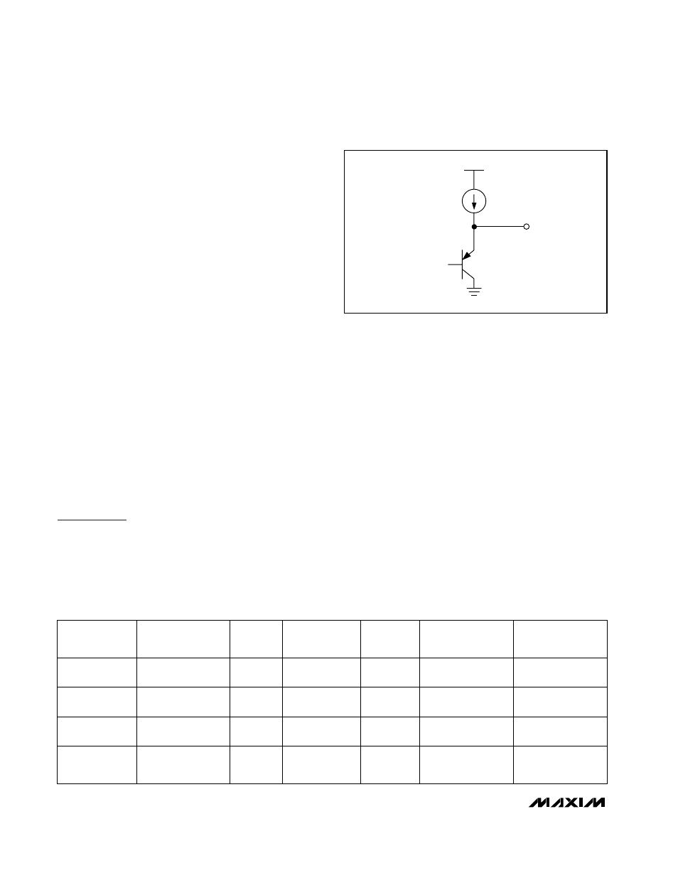
Reference (MAX917/MAX918)
The internal reference in the MAX917/MAX918 has an
output voltage of +1.245V with respect to V
EE
. Its typi-
cal temperature coefficient is 95ppm/°C over the full
-40°C to +85°C temperature range. The reference is a
PNP emitter-follower driven by a 120nA current source
(Figure 1). The output impedance of the voltage refer-
ence is typically 200k
Ω
, preventing the reference from
driving large loads. The reference can be bypassed
with a low-leakage capacitor. The reference is stable
for any capacitive load. For applications requiring a
lower output impedance, buffer the reference with a
low-input-leakage op amp, such as the MAX406.
Applications Information
Low-Voltage, Low-Power Operation
The MAX917–MAX920 are ideally suited for use with most
battery-powered systems. Table 1 lists a variety of battery
types, capacities, and approximate operating times for
the MAX917–MAX920, assuming nominal conditions.
Internal Hysteresis
Many comparators oscillate in the linear region of oper-
ation because of noise or undesired parasitic feed-
back. This tends to occur when the voltage on one
input is equal or very close to the voltage on the other
input. The MAX917–MAX920 have internal hysteresis to
counter parasitic effects and noise.
The hysteresis in a comparator creates two trip points:
one for the rising input voltage (V
THR
) and one for the
falling input voltage (V
THF
) (Figure 2). The difference
between the trip points is the hysteresis (V
HB
). When
the comparator’s input voltages are equal, the hystere-
sis effectively causes one comparator input to move
quickly past the other, thus taking the input out of the
region where oscillation occurs. Figure 2 illustrates the
case in which IN- has a fixed voltage applied, and IN+
is varied. If the inputs were reversed, the figure would
be the same, except with an inverted output.
MAX917–MAX920
SOT23, 1.8V, Nanopower, Beyond-the-Rails
Comparators With/Without Reference
10
______________________________________________________________________________________
120nA
REF
V
CC
V
EE
Figure 1. MAX917/MAX918 Voltage Reference Output
Equivalent Circuit
No
Alkaline
(2 Cells)
Yes
Lithium-Ion
(1 Cell)
Yes
Nickel-Metal-
Hydride
(2 Cells)
Yes
Nickel-Cadmium
(2 Cells)
3.0
3.5
2.4
2.4
1.8
2.7
1.8
1.8
V
END-OF-LIFE
(V)
V
FRESH
(V)
BATTERY
TYPE
RECHARGEABLE
2000
1000
1000
750
2.5 x 10
6
1.25 x 10
6
1.25 x 10
6
937,500
5 x 10
6
2.5 x 10
6
2.5 x 10
6
1.875 x 10
6
MAX919/MAX920
OPERATING TIME
(hr)
MAX917/MAX918
OPERATING TIME
(hr)
CAPACITY,
AA SIZE
(mA-h)
Table 1. Battery Applications Using MAX917–MAX920