And 4.5-digit, single-chip adcs with lcd drivers – Rainbow Electronics MAX1494 User Manual
Page 12
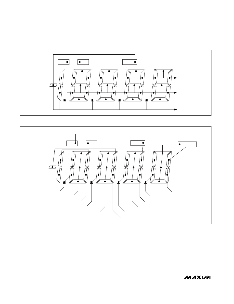
MAX1492/MAX1494
and 5 show the assignment of the 4.5-digit display seg-
ments, and Figures 6 and 7 show the assignment of the
3.5-digit display segments.
The voltage waveforms of the backplane lines and Y
segment line (Figure 3) have been chosen as an exam-
ple. This line intersects with BP1 to form the a segment,
with BP2 to form the g segment, and with BP3 to form
the d segment. Eight different ON/OFF combinations of
the a, g, and d segments and their corresponding
waveforms of the Y segment line are illustrated in
Figures 9 and 10. The schematic diagram in Figure 8
shows each intersection as a capacitance from seg-
ment line to common line. Figure 11 illustrates the volt-
age across the g segment.
The RMS voltage across the segment determines the
degree of polarization for the liquid crystal material and
3.5- and 4.5-Digit, Single-Chip ADCs
with LCD Drivers
12
______________________________________________________________________________________
HOLD
LOW BATT
PEAK
BP1
BP2
BP3
Figure 4. Backplane Connection for the MAX1494 (4.5 Digits)
HOLD
LOW BATT
PEAK
SEG13: PEAK, HOLD, N.C.
SEG2: A1, G1, D1
SEG12: F4, E4, DP4
SEG11: A4, G4, D4
SEG10: B4, C4, BC5
SEG9: F3, E3, DP3
SEG8: A3, G3, D3
SEG1: B1, C1, N.C.
SEG3: F1, E1, DP1
SEG4: B2, C2, LOWBATT
SEG5: A2, G2, D2
SEG6: F2, E2, DP2
SEG7: B3, C3, MINUS
ANNUNCIATOR
Figure 5. Segment Connection for the MAX1494 (4.5 Digits)