Rainbow Electronics MAX1249 User Manual
Page 11
MAX1248/MAX1249
+2.7V to +5.25V, Low-Power, 4-Channel,
Serial 10-Bit ADCs in QSOP-16
______________________________________________________________________________________
11
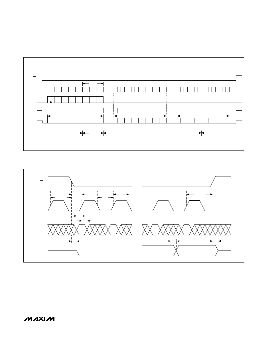
CS goes high; after the next CS falling edge, SSTRB will
output a logic low. Figure 7 shows the SSTRB timing in
external clock mode.
The conversion must complete in some minimum time,
or droop on the sample-and-hold capacitors may
degrade conversion results. Use internal clock mode if
the serial-clock frequency is less than 100kHz, or if
serial-clock interruptions could cause the conversion
interval to exceed 120µs.
• • •
• • •
• • •
• • •
CS
SCLK
DIN
DOUT
t
CSH
t
CSS
t
CL
t
DS
t
DH
t
DV
t
CH
t
DO
t
TR
t
CSH
Figure 6. Detailed Serial-Interface Timing
SSTRB
CS
SCLK
DIN
DOUT
1
4
8
12
16
20
24
START
SEL2 SEL1 SEL0
UNI/
BIP
SGL/
DIF
PD1 PD0
B9
MSB
B8
B7
B6
B5
B4
B3
B2
B1
B0
LSB
S1
S0
ACQUISITION
(f
CLK
= 2MHz)
IDLE
FILLED WITH
ZEROS
IDLE
CONVERSION
t
ACQ
A/D STATE
RB1
RB2
RB3
1.5µs
Figure 5. 24-Clock External Clock Mode Conversion Timing (MICROWIRE and SPI-Compatible, QSPI-Compatible with f
SCLK
≤
2MHz)