Applications information, Table 5. data-bus output (8+2 parallel interface) – Rainbow Electronics MAX1093 User Manual
Page 15
MAX1091/MAX1093
250ksps, +3V, 8-/4-Channel, 10-Bit ADCs
with +2.5V Reference and Parallel Interface
______________________________________________________________________________________
15
Table 4. Channel Selection for Pseudo-Differential Operation (SGL/DIF = 0)
*Channels CH4–CH7 apply to MAX1091 only.
A1
CH0
0
+
0
-
0
A0
0
-
1
CH2
CH4*
+
0
1
0
+
-
CH3
0
CH1
CH7*
CH6*
1
CH5*
1
-
+
0
0
0
A2
+
-
1
0
1
-
+
1
1
0
-
1
1
1
+
1
+
-
Applications Information
Power-On Reset
When power is first applied, internal power-on reset cir-
cuitry activates the MAX1091/MAX1093 in external
clock mode and sets INT high. After the power supplies
stabilize, the internal reset time is 10µs, and no conver-
sions should be attempted during this phase. When
using the internal reference, 500µs is required for V
REF
to stabilize.
Internal and External Reference
The MAX1091/MAX1093 can be used with an internal
or external reference voltage. An external reference
can be connected directly to REF or REFADJ.
An internal buffer is designed to provide +2.5V at REF for
the both the MAX1091 and the MAX1093. The internally
trimmed +1.22V reference is buffered with a +2.05V/V
gain.
Internal Reference
With the internal reference, the full-scale range is +2.5V
with unipolar inputs and ±1.25V with bipolar inputs. The
internal reference buffer allows for small adjustments
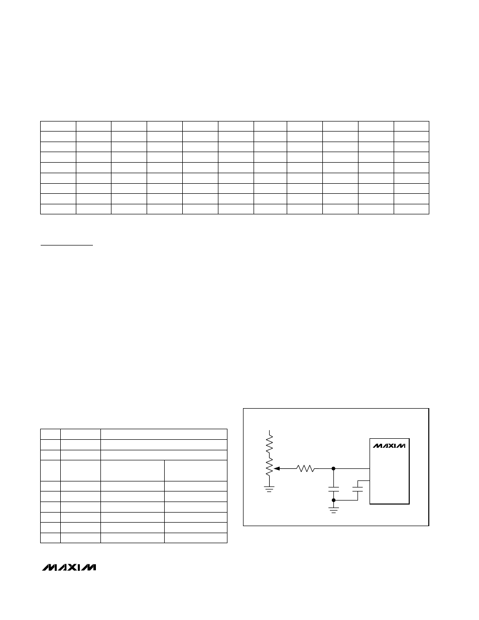
(±100mV) in the reference voltage (Figure 7).
Note: The reference buffer must be compensated with
an external capacitor (4.7µF min) connected between
REF and GND to reduce reference noise and switching
spikes from the ADC. To further minimize noise on the
reference, connect a 0.01µF capacitor between
REFADJ and GND.
External Reference
With both the MAX1091 and MAX1093, an external ref-
erence can be placed at either the input (REFADJ) or
the output (REF) of the internal reference buffer amplifier.
Using the REFADJ input makes buffering the external
reference unnecessary. The REFADJ input impedance
is typically 17k
Ω.
Table 5. Data-Bus Output (8+2 Parallel
Interface)
UNIPOLAR
(UNI/BIP = 1)
BIPOLAR
(UNI/BIP = 0)
0
0
0
D6
D7
Bit 9
Bit 7
Bit 9
Bit 6
D2
Bit 9
Bit 2
D1
Bit 9 (MSB)
Bit 1
HBEN = 1
Bit 8
HBEN = 0
Bit 0 (LSB)
PIN
D0
V
DD
= +3V
330k
50k
GND
50k
0.01µF
4.7µF
REFADJ
REF
MAX1091
MAX1093
GND
Figure 7. Reference Voltage Adjustment with External
Potentiometer
0
D3
Bit 9
Bit 3
0
D4
Bit 9
Bit 4
0
D5
Bit 9
Bit 5