Detailed description, Start-up, Dc-dc 1 boost converter – Rainbow Electronics MAX1664 User Manual
Page 8: Typical operating characteristics
MAX1664
Active-Matrix Liquid Crystal Display
(AMLCD) Supply
8
_______________________________________________________________________________________
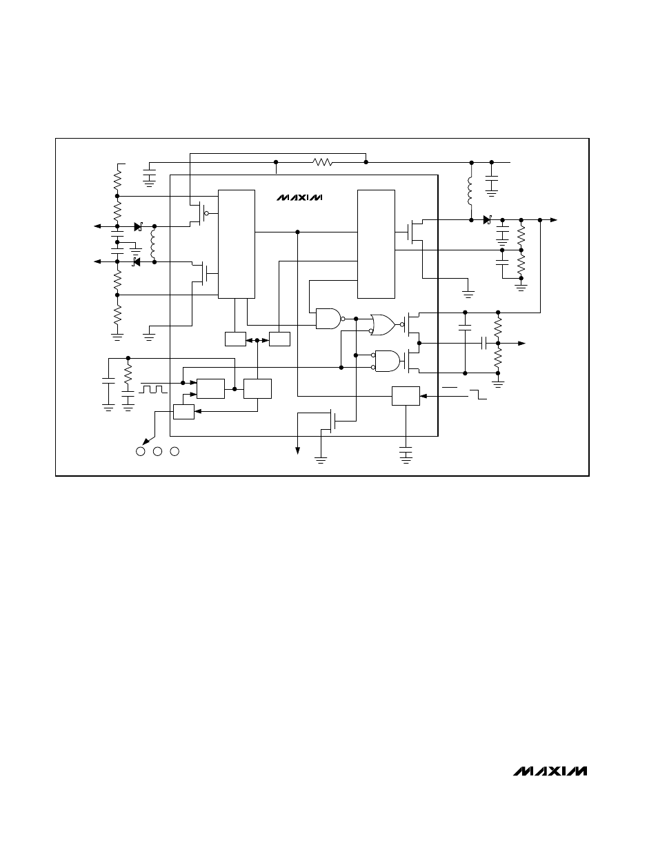
_______________Detailed Description
The MAX1664 combines power supply and backplane
drive circuitry for active matrix thin-film-transistor (TFT)
liquid crystal displays (LCD) into one IC. Included are a
pulse-width-modulation (PWM) boost converter, a dual-
output (positive and negative) converter using one
inductor, an LCD backplane driver, and a phase-
locked loop (PLL) to synchronize all three outputs to the
backplane clock.
A high switching frequency (1MHz nominal) and phase-
locked operation allow the use of small, minimum-
height external components while maintaining low
output noise. Output voltages are adjustable to +5.5V
(DC-DC 1) and to +28V and -10V (DC-DC 2). The nega-
tive output voltage can be set to as low as -20V with
additional components.
The frequency ratio between the DC-DC 1 converter
and the backplane clock can be set to 16, 24, or 32.
This flexibility allows high DC-DC converter frequencies
to be used with LCD backplane clock rates ranging
from 20kHz to 72kHz.
Start-Up
At start-up, both converters remain disabled until V
REF
reaches 90% of its nominal value. V
OUT1
is activated
first. Once V
OUT1
is regulated, V
OUT2-
is enabled.
V
OUT2+
is held at 0 until V
OUT2-
is within 90% of its reg-
ulation target. All three outputs power up in a similar
order when power is applied or when coming out of
shutdown. See the Out-of-Shutdown Sequence photo in
the
Typical Operating Characteristics
section.
DC-DC 1 Boost Converter
DC-DC 1 uses a current-mode boost PWM architecture
to produce a positive regulated voltage, adjustable
from 3V to 5.5V (but not less than V
IN
). This converter
uses an internal N-channel MOSFET with a maximum
on-resistance of 0.5
Ω
. Cycle-by-cycle peak current lim-
iting protects the switch under fault conditions. Upon
start-up, DC-DC 1 is the first converter to be enabled.
BACKPLANE
DRIVER
BPV
SS
BPDRV
BPV
DD
PGND1
FB1
LX1
V
SUPPLY
2.8V TO 5.5V
V
OUT1
5.5V
SHDN
REF
1.25V
REF
PHASE
DET
VCO
ч
4
ч
2
ч
N
FPLL
BPCLK
PLLC
PGND2
FB2+
LX2N
DC-DC 2
DC-DC 1
LX2P
INP
IN
FB2-
REF
V
OUT2-
-10V
V
OUT2+
28V
IN
REF
GND
GND
RDY
MAX1664
Figure 1. Functional Diagram