Rainbow Electronics MAX1664 User Manual
Page 10
MAX1664
Active-Matrix Liquid Crystal Display
(AMLCD) Supply
10
______________________________________________________________________________________
The heart of the PLL is the VCO, which is trimmed to a
nominal frequency of 1.92MHz for a control voltage (at
the PLLC pin) of 1.250V. This high-frequency internal
clock is divided digitally with a division ratio selected
by pin-strapping FPLL to GND, REF, or IN. This divided
clock is compared to the backplane clock by an inter-
nal phase comparator (rising-edge triggered). The
phase detector in turn adjusts the VCO control voltage
until the two frequencies (and phases) match. This
feedback loop is compensated at the PLLC pin.
In some applications, the backplane clock may be halt-
ed for several cycles between screen scans or may not
be immediately applied on power-up. The PLL contains
a proprietary phase-detector architecture that mini-
mizes frequency error during clock dropouts of more
than two cycles and re-establishes lock immediately
when the clock resumes.
Ready Indicator (RDY)
The RDY pin has an open-drain output and indicates
when all three outputs are in regulation. The open-drain
output becomes high impedance when all three convert-
er outputs are within 10% of their regulation setpoints.
Design Procedure and
______________Component Selection
Output Voltage Selection
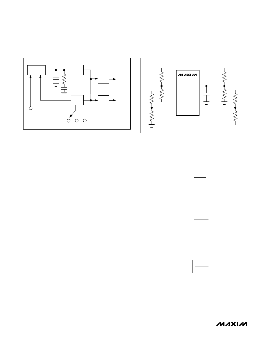
The three output voltages as well as the DC bias for the
backplane clock are adjustable on the MAX1664, as
shown in Figure 3. Set each output using two standard
1% resistors to form a voltage divider between the
selected output and its respective feedback pin. Use
the following equations to calculate the resistances.
DC-DC 1 Output
For V
OUT1
= 5V, typical values are R2 = 100k
Ω
and R1
= 301k
Ω
. To set V
OUT1
to another voltage, choose R2 =
100k
Ω
and C
FB1
= 50pF, and calculate R1 as follows:
DC-DC 2 Positive Output
For V
OUT2+
= 15V, typical values are R8 = 49.9k
Ω
and
R7 = 549k
Ω
. To set V
OUT2+
to another voltage, choose
R8 = 49.9k
Ω
and calculate R7 as follows:
DC-DC 2 Negative Output
For the negative output voltage, the FB2- threshold volt-
age is 0. For V
OUT2-
= -5V, typical values are R5 =
49.9k
Ω
and R6 = 200k
Ω
. To set V
OUT2+
to another volt-
age, choose R5 = 49.9k
Ω
and calculate R6 as follows:
DC Bias for the Backplane Driver
For V
DCBIAS
= V
BPVDD
/2, typical values are R3 = R4 =
100k
Ω
. To set the DC bias to a different value, choose
R4 and calculate R3 as follows:
R3
R4
V
- V
V
- V
- 1
BPVDD
BPVSS
DCBIAS
BPVSS
=
R6
R5
V
V
OUT2-
REF
=
R7
R8
V
V
- 1
OUT2
FB2
=
+
+
R1
R2
V
V
- 1
OUT1
FB1
=
PHASE
DETECTOR
VCO
ч
4
ч
2
PLLC
÷
N*
IN
REF
BPCLK
*SEE TABLE 1 FOR
SELECTED VALUES OF N.
DC-DC 1
R
PLLC
C
PLLC
C
SHUNT
DC-DC 2
GND
Figure 2. Internal PLL Operation within the MAX1664
BPV
DD
C
FB1
R2
R1
FB2+
FB2-
BPDRV
FB1
R5
R6
V
OUT2-
R7
R8
REF
BPV
SS
C
C
V
OUT1
V
OUT2+
R3
DC
BIAS
R4
MAX1664
Figure 3. Output Voltage Selection