Supply connections and layout – Rainbow Electronics MAX1664 User Manual
Page 14
MAX1664
Active-Matrix Liquid Crystal Display
(AMLCD) Supply
14
______________________________________________________________________________________
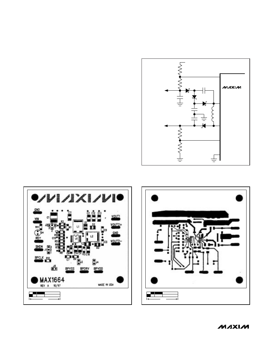
Figure 7a. MAX1664 Component Placement Guide
Figure 7b. MAX1664 PC Board Layout—Component Side
1.0"
1.0"
Supply Connections and Layout
The MAX1664 performs both precision analog and
high-power switching functions. Carefully plan supply
connections, bypassing, and layout. Bypass IN and INP
with a 33
Ω
isolation resistor (R9, Figure 4) between
them. In addition, sufficient low-ESR bypassing must be
provided on the INP bus to ensure stability of DC-DC 1.
A solid ground plane under the power components,
with a separate ground plane under the analog nodes,
is highly recommended. These ground planes should
be connected at a single, quiet point. Analog reference
and feedback signals should be referred to and routed
over the analog ground plane. Figure 7 shows a typical
layout using separate ground planes.
REF
R5
R6
R7
R8
FB2-
LX2P
L2
LX2N
FB2+
D3
D2
D5
D4
C
F
V1
PGND2
0.47
µ
F
0.22
µ
F
C
OUT
4.7
µ
F
V
OUT2-
-20V
V
OUT2+
28V
MAX1664
Figure 6. V
OUT2
- Voltage-Doubler Charge Pump