3 t_crit_a output and t_crit limit, Figure 6. t_crit_a temperature response diagram, 4 power on reset default states – Rainbow Electronics LM86 User Manual
Page 9: 5 smbus interface, 6 temperature data format, 0 functional description
1.0 Functional Description
(Continued)
1.
Master Senses SMBus alert line low
2.
Master sends a START followed by the Alert Response
Address (ARA) with a Read Command.
3.
Alerting Device(s) send ACK.
4.
Alerting Device(s) send their Address. While transmitting
their address, alerting devices sense whether their ad-
dress has been transmitted correctly. (The LM86 will
reset its ALERT output and set the ALERT mask bit once
its complete address has been transmitted successfully.)
5.
Master/slave NoACK
6.
Master sends STOP
7.
Master attends to conditions that caused the ALERT to
be triggered. The STATUS REGISTER is read and fan
started, setpoint limits adjusted, etc.
8.
Master resets the ALERT mask (D7 in the Configuration
register).
The ARA, 000 1100, is a general call address. No device
should ever be assigned this address.
Bit D0 (the ALERT configure bit) in the FILTER and ALERT
CONFIGURE REGISTER (xBF) must be set low in order for
the LM86 to respond to the ARA command.
The ALERT output can be disabled by setting the ALERT
mask bit, D7, of the Configuration register. The power on
default is to have the ALERT mask bit and the ALERT
configure bit low.
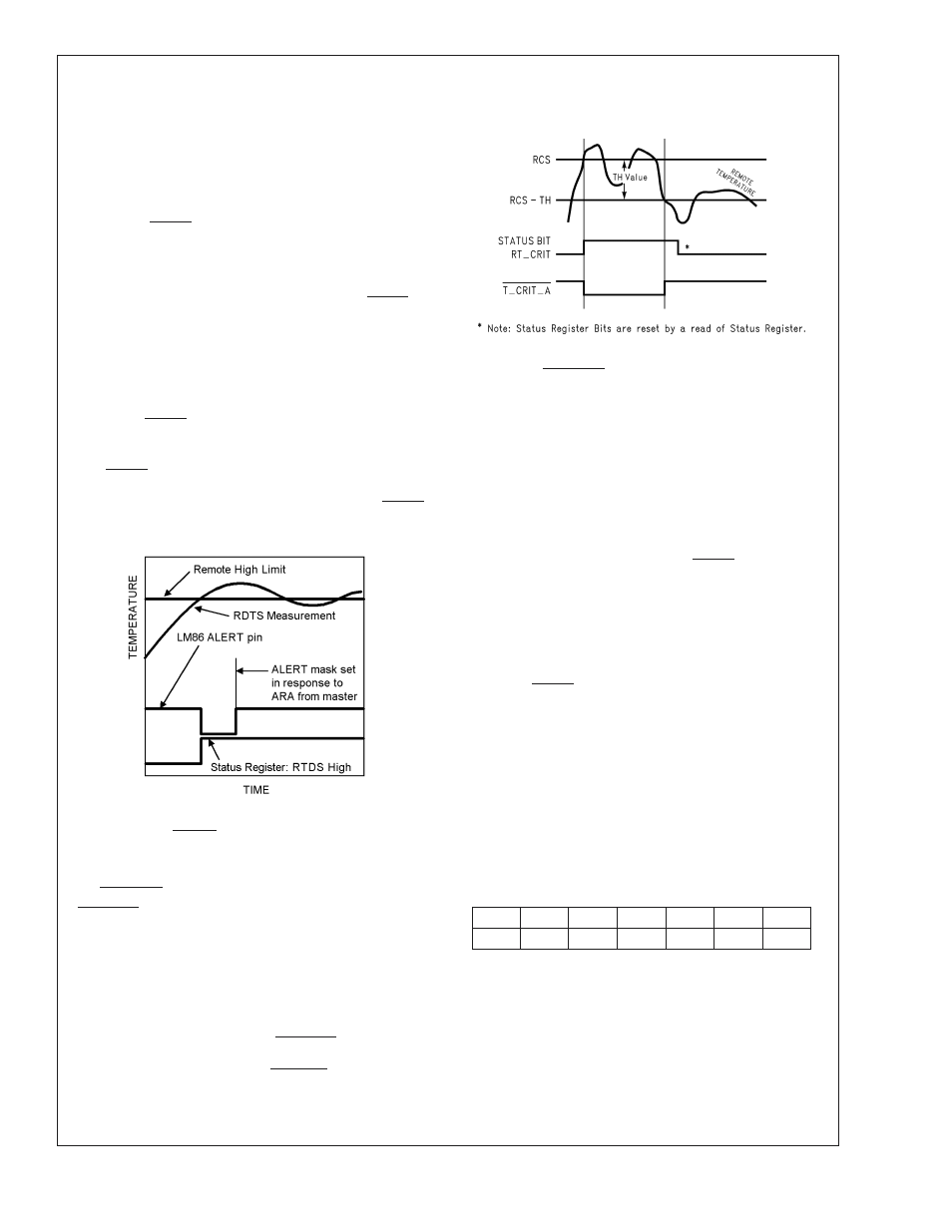
1.3 T_CRIT_A OUTPUT and T_CRIT LIMIT
T_CRIT_A is activated when any temperature reading is
greater than the limit preset in the critical temperature set-
point register (T_CRIT), as shown in Figure 6. The Status
Register can be read to determine which event caused the
alarm. A bit in the Status Register is set high to indicate
which temperature reading exceeded the T_CRIT setpoint
temperature and caused the alarm, see Section 2.3.
Local and remote temperature diodes are sampled in se-
quence by the A/D converter. The T_CRIT_A output and the
Status Register flags are updated after every Local and
Remote temperature conversion. T_CRT_A follows the state
of the comparison, it is reset when the temperature falls
below the setpoint RCS-TH. The Status Register flags are
reset only after the Status Register is read and if a tempera-
ture conversion(s) is/are below the T_CRIT setpoint, as
shown in . Figure 6
1.4 POWER ON RESET DEFAULT STATES
LM86 always powers up to these known default states. The
LM86 remains in these states until after the first conversion.
1.
Command Register set to 00h
2.
Local Temperature set to 0˚C
3.
Remote Diode Temperature set to 0˚C until the end of
the first conversion.
4.
Status Register set to 00h.
5.
Configuration register set to 00h; ALERT enabled, Re-
mote T_CRIT alarm enabled and Local T_CRIT alarm
enabled
6.
85˚C Local and Remote T_CRIT temperature setpoints
7.
70˚C Local and Remote HIGH temperature setpoints
8.
0˚C Local and Remote LOW temperature setpoints
9.
Filter and Alert Configure Register set to 00h; filter dis-
abled, ALERT output set as an SMBus ALERT
10. Conversion Rate Register set to 8h; conversion rate set
to 16 conv./sec.
1.5 SMBus INTERFACE
The LM86 operates as a slave on the SMBus, so the
SMBCLK line is an input and the SMBData line is bi-
directional. The LM86 never drives the SMBCLK line and it
does not support clock stretching. According to SMBus
specifications, the LM86 has a 7-bit slave address. All bits A6
through A0 are internally programmed and can not be
changed by software or hardware.
The complete slave address is:
A6
A5
A4
A3
A2
A1
A0
1
0
0
1
1
0
0
1.6 TEMPERATURE DATA FORMAT
Temperature data can only be read from the Local and
Remote Temperature
registers;
the
setpoint
registers
(T_CRIT, LOW, HIGH) are read/write.
Remote temperature data is represented by an 11-bit, two’s
complement word with an LSB (Least Significant Bit) equal
to 0.125˚C. The data format is a left justified 16-bit word
available in two 8-bit registers:
10130329
FIGURE 5. ALERT Output as an SMBus ALERT
Temperature Response Diagram
10130306
FIGURE 6. T_CRIT_A Temperature Response Diagram
LM86
www.national.com
9