Figure 1. esd protection input structure, Note 1), Note – Rainbow Electronics LM86 User Manual
Page 6: Note 2), Note 4), Note 6), Note 7), Lm86
SMBus DIGITAL SWITCHING CHARACTERISTICS Unless otherwise noted, these specifications apply for V
DD
=+3.0 Vdc to
+3.6 Vdc, C
L
(load capacitance) on output lines = 80 pF. Boldface limits apply for T
A
= T
J
= T
MIN
to T
MAX
; all other limits
T
A
= T
J
= +25˚C, unless otherwise noted. The switching characteristics of the LM86 fully meet or exceed the published specifi-
cations of the SMBus version 2.0. The following parameters are the timing relationships between SMBCLK and SMBData sig-
nals related to the LM86. They adhere to but are not necessarily the SMBus bus specifications.
Symbol
Parameter
Conditions
Typical
Limits
Units
(Limit)
t
BUF
SMBus Free Time Between Stop and Start
Conditions
1.3
µs (min)
SMBus Communication
10130340
Note 1: Absolute Maximum Ratings indicate limits beyond which damage to the device may occur. DC and AC electrical specifications do not apply when operating
the device beyond its rated operating conditions.
Note 2: When the input voltage (V
I
) at any pin exceeds the power supplies (V
I
<
GND or V
I
>
V
DD
), the current at that pin should be limited to 5 mA.
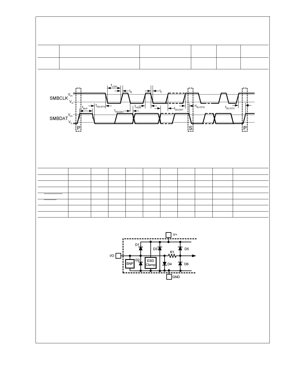
Parasitic components and or ESD protection circuitry are shown in the figure below for the LM86’s pins. The nominal breakdown voltage of D3 is 6.5 V. Care should
be taken not to forward bias the parasitic diode, D1, present on pins: D+, D−. Doing so by more than 50 mV may corrupt a temperature measurements.
Pin Name
PIN #
D1
D2
D3
D4
D5
D6
R1
SNP
ESD CLAMP
V
DD
(V+)
1
x
x
D+
2
x
x
x
x
x
x
D−
3
x
x
x
x
x
x
T_CRIT_A
4
x
x
x
ALERT
6
x
x
x
SMBData
7
x
x
x
SMBCLK
8
x
Note: An “x” indicates that the diode exists.
Note 3: See the URL ”http://www.national.com/packaging/“ for other recommendations and methods of soldering surface mount devices.
Note 4: Human body model, 100pF discharged through a 1.5k
Ω resistor. Machine model, 200pF discharged directly into each pin.
Note 5: Thermal resistance junction-to-ambient when attached to a printed circuit board with 2 oz. foil:
– SOIC-8 = 168˚C/W
– MSOP-8 = 210˚C/W
Note 6: Typicals are at T
A
= 25˚C and represent most likely parametric norm.
Note 7: Limits are guaranteed to National’s AOQL (Average Outgoing Quality Level).
10130313
FIGURE 1. ESD Protection Input Structure
LM86
www.national.com
6