Figure 12, Figure 13, Figure 14 – Rainbow Electronics LM86 User Manual
Page 18: 0 application hints, Lm86
3.0 Application Hints
(Continued)
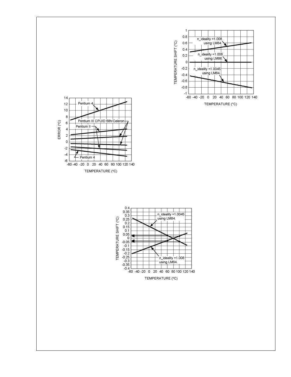
mobile Pentium III processor, 1.008. When a temperature
sensor calibrated for a particular processor type is used with
a different processor type or a given processor type has a
non-ideality that strays from the typical, errors are intro-
duced. Figure 12 shows the minimum and maximum errors
introduced to a temperature sensor calibrated specifically to
the typical value of the processor type it is connected to. The
errors in this figure are attributed only to the variation in
non-ideality from the typical value. In Figure 13 is a plot of
the errors that result from using a temperature sensor cali-
brated for a Pentium II, the LM84, with a typical Pentium 4 or
AMD Athlon MP Model 6.
Temperature errors associated with non-ideality may be re-
duced in a specific temperature range of concern through
use of the offset registers (11h and 12h). Figure 14 shows
how the offset register may be used to compensate for the
non-ideality errors shown in Figure 13. For the case of
non-ideality=1.008, the offset register was set to −0.5˚C
resulting in the calculated residual error as shown in Figure
14. This offset has resulted in an error of less than 0.05˚C for
the temperatures measured in the critical range between 60
to 100˚C. This method yeilds a first order correction factor.
Please send an email to hardware.monitor.team
@
nsc.com
requesting further information on our recommended setting
of the offset register for different processor types.
10130337
Error Caused by Non-Ideality Factor
FIGURE 12.
10130336
Errors Induced when Temperature Sensor is Not
Calibrated to Typical Non-Ideality
FIGURE 13.
10130338
Compensating for an Untargeted Non-Ideality Factor
FIGURE 14.
LM86
www.national.com
18