1 smbus timing diagrams, Figure 7. smbus timing diagrams, 10 serial interface reset – Rainbow Electronics LM86 User Manual
Page 11: 11 digital filter, 0 functional description, Lm86
1.0 Functional Description
(Continued)
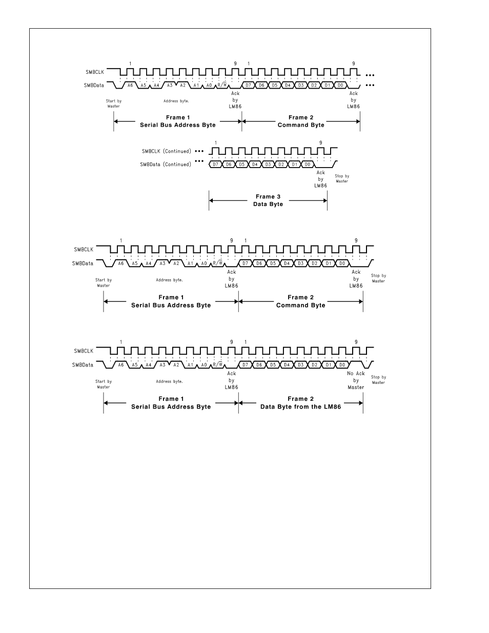
1.9.1 SMBus Timing Diagrams
1.10 SERIAL INTERFACE RESET
In the event that the SMBus Master is RESET while the
LM86 is transmitting on the SMBData line, the LM86 must be
returned to a known state in the communication protocol.
This may be done in one of two ways:
1.
When SMBData is LOW, the LM86 SMBus state ma-
chine resets to the SMBus idle state if either SMBData
or SMBCLK are held low for more than 35ms (t
TIMEOUT
).
Note that according to SMBus specification 2.0 all de-
vices are to timeout when either the SMBCLK or SMB-
Data lines are held low for 25-35ms. Therefore, to insure
a timeout of all devices on the bus the SMBCLK or
SMBData lines must be held low for at least 35ms.
2.
When SMBData is HIGH, have the master initiate an
SMBus start. The LM86 will respond properly to an
SMBus start condition at any point during the communi-
cation. After the start the LM86 will expect an SMBus
Address address byte.
1.11 DIGITAL FILTER
In order to suppress erroneous remote temperature readings
due to noise, the LM86 incorporates a user-configured digital
filter. The filter is accessed in the FILTER and ALERT CON-
FIGURE REGISTER at BFh. The filter can be set according
to the following table.
10130310
(a) Serial Bus Write to the internal Command Register followed by a the Data Byte
10130311
(b) Serial Bus Write to the Internal Command Register
10130312
(c) Serial Bus Read from a Register with the Internal Command Register preset to desired value.
FIGURE 7. SMBus Timing Diagrams
LM86
www.national.com
11