Figure 8. filter output response to a step input, 0 functional description – Rainbow Electronics LM86 User Manual
Page 12
1.0 Functional Description
(Continued)
D2
D1
Filter
0
0
No Filter
0
1
Level 1
1
0
Level 1
1
1
Level 2
Level 2 sets maximum filtering.
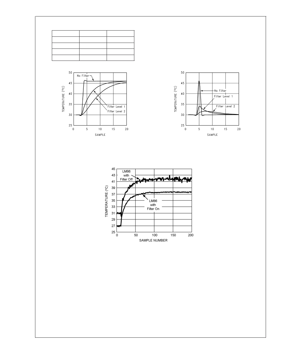
Figure 8 depict the filter output to in response to a step input
and an impulse input. Figure 9 depicts the digital filter in use
in a Pentium 4 processor system. Note that the two curves,
with filter and without, have been purposely offset so that
both responses can be clearly seen. Inserting the filter does
not induce an offset as shown.
10130325
a)Step Response
10130326
b)Impulse Response
FIGURE 8. Filter Output Response to a Step Input
10130327
FIGURE 9. Digital Filter Response in a Pentium 4 processor System. The filter on and off curves were purposely
offset to better show noise performance.
LM86
www.national.com
12
See also other documents in the category Rainbow Electronics Sensors:
- MAX5151 (16 pages)
- MAXQ3108 (64 pages)
- MAX5661 (39 pages)
- MAX6691 (7 pages)
- MAX5362 (12 pages)
- ADC10158 (26 pages)
- MAX8922L (14 pages)
- MAX8596Z (8 pages)
- MAX7491 (18 pages)
- MAX15040 (15 pages)
- MAX5177 (16 pages)
- ADC08138 (22 pages)
- MAX5961 (42 pages)
- T89C51RD2 (86 pages)
- MAX16055 (9 pages)
- MAX6659 (17 pages)
- ADC0820 (20 pages)
- MAX6678 (19 pages)
- MAX8884Z (15 pages)
- MAX16915 (9 pages)
- MAX8620 (18 pages)
- MAX5144 (12 pages)
- MAX6670 (8 pages)
- MAX8760 (39 pages)
- W78C32C (14 pages)
- MX7533 (8 pages)
- MAX8727 (13 pages)
- MAX9053 (15 pages)
- W78C54 (16 pages)
- MAX8614B (15 pages)
- W90N740 (219 pages)
- MAX6626 (13 pages)
- ADC10738 (30 pages)
- MAX17000 (31 pages)
- MAX5051 (21 pages)
- MAXQ1004 (18 pages)
- MAX6871 (51 pages)
- MX7847 (12 pages)
- MAX6608 (6 pages)
- MAX17083 (15 pages)
- MAX6641 (17 pages)
- MAX5251 (16 pages)
- MAX6338 (8 pages)
- MAX6690 (16 pages)
- MAX8668 (18 pages)