Max3983 quad copper-cable signal conditioner, Pin description – Rainbow Electronics MAX3983 User Manual
Page 9
MAX3983
Quad Copper-Cable Signal Conditioner
_______________________________________________________________________________________
9
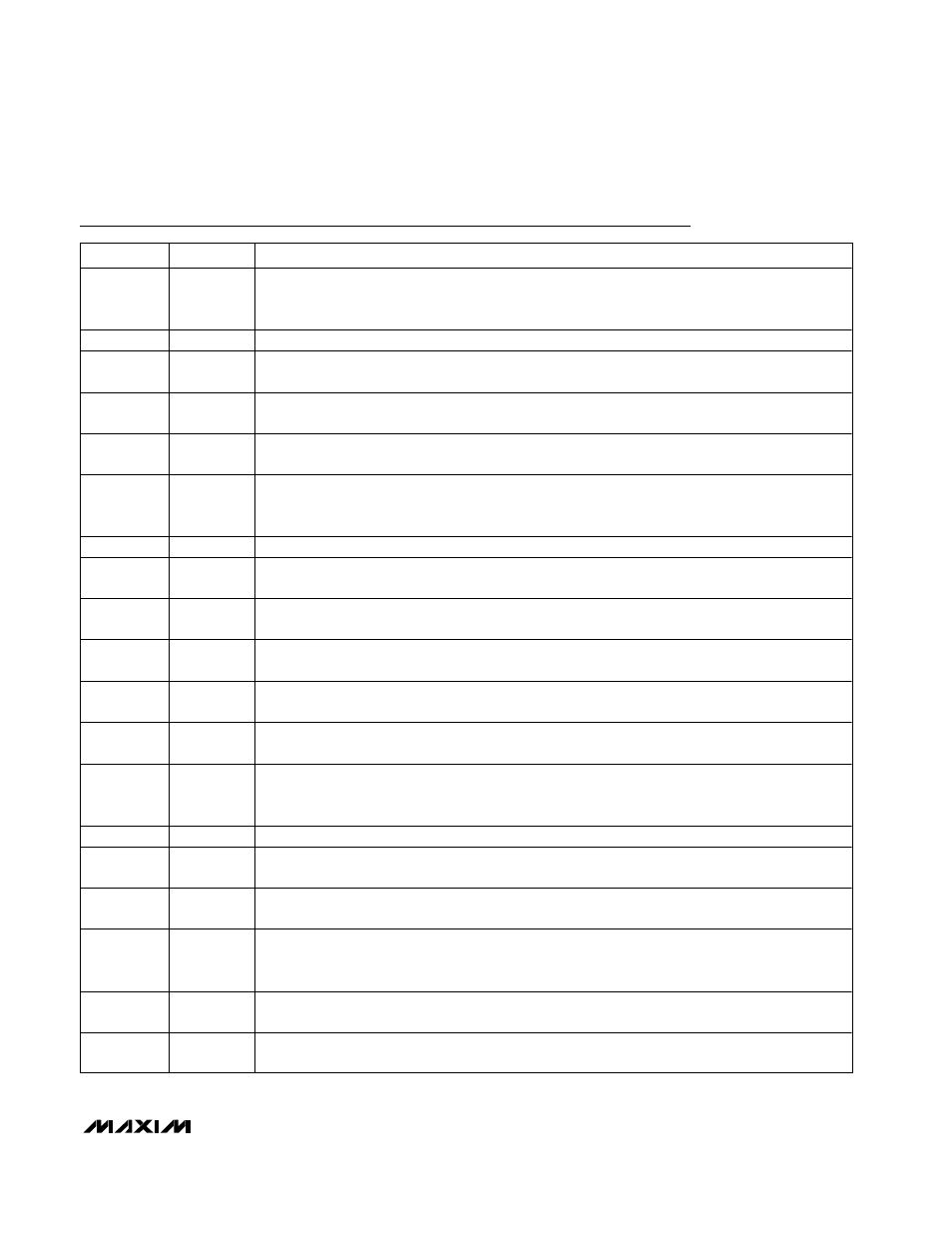
Pin Description
PIN
NAME
FUNCTION
1, 2, 16, 17
TX_SD1 to
TX_SD4
PC Board Receiver Signal Detect, TTL Output. This output is open-collector TTL, and therefore
requires an external 4.7k
Ω to 10kΩ pullup resistor to V
CC
. These outputs sink current when the input
signal level is not valid.
3, 15
V
CC
1
Power-Supply Connection for TX Inputs. Connect to +3.3V.
4, 7, 10, 13
TX_IN1- to
TX_IN4-
PC Board Receiver Negative Data Inputs, CML. These inputs are internally differentially terminated to
the corresponding TX_IN+ with 100
Ω.
5, 8, 11, 14
TX_IN1+ to
TX_IN4+
PC Board Receiver Positive Data Inputs, CML. These inputs are internally differentially terminated to
the corresponding TX_IN- with 100
Ω.
6, 9, 12, 40,
43, 46
GND
Circuit Ground
18
TX_ENABLE
Cable Transmitter Enable Input, LVTTL with 40k
Ω Internal Pullup. This pin enables all four cable
transmitter outputs TX_OUT[1:4]. When low, differential output is less than 30mV
P-P
. Set high or open
for normal operation.
19
N.C.
No Connection. Do not connect this pin.
20, 23, 26,
29, 32
V
CC
2
Power-Supply Connection for TX Outputs. Connect to +3.3V.
21, 24, 27,
30
TX_OUT1+ to
TX_OUT4+
Cable Transmitter Positive Data Outputs, CML. These outputs are terminated with 50
Ω to V
CC
2.
22, 25, 28,
31
TX_OUT1- to
TX_OUT4-
Cable Transmitter Negative Data Outputs, CML. These outputs are terminated with 50
Ω to V
CC
2.
33
TX_PE0
Cable Transmitter Preemphasis Control Input, LVTTL with 40k
Ω Internal Pullup. This pin is the least
significant bit of the 2-bit preemphasis control. Set high or open to assert this bit.
34
TX_PE1
Cable Transmitter Preemphasis Control Input, LVTTL with 40k
Ω Internal Pullup. This pin is the most
significant bit of the 2-bit preemphasis control. Set high or open to assert this bit.
35, 36, 50,
51
RX_SD4 to
RX_SD1
Cable Receiver Signal Detect, TTL Output. This output is open-collector TTL, and therefore it requires
an external 4.7k
Ω to 10kΩ pullup resistor to V
CC
. These outputs sink current when the input signal
level is not valid.
37, 49
V
CC
3
Power-Supply Connection for RX Inputs. Connect to +3.3V.
38, 41, 44,
47
RX_IN4- to
RX_IN1-
Cable Receiver Negative Data Inputs, CML. These inputs are internally differentially terminated to the
corresponding RX_IN+ with 100
Ω.
39, 42, 45,
48
RX_IN4+ to
RX_IN1+
Cable Receiver Positive Data Inputs, CML. These inputs are internally differentially terminated to the
corresponding RX_IN- with 100
Ω.
52
RX_ENABLE
PC Board Transmitter Enable Input, LVTTL with 40k
Ω Internal Pullup. This pin enables all four PC
board transmitter outputs RX_OUT[1:4]. When low, differential output is less than 30mV
P-P
. Set high
or open for normal operation.
53
POR
Power-On Reset Connection. Connect external capacitor 0.1µF
≤ C
POR
≤ 10µF to ground. See the
Detailed Description.
54, 57, 60,
63, 66
V
CC
4
Power-Supply Connection for RX Outputs. Connect to +3.3V.