Max3983 quad copper-cable signal conditioner, Interface schematics – Rainbow Electronics MAX3983 User Manual
Page 13
MAX3983 will produce excessive crosstalk in InfiniBand
and CX4 cable assemblies.
Crosstalk
For InfiniBand and 10Gbase-CX4 applications, it is
imperative to know the near-end crosstalk characteristics
of the cable assemblies. 10Gbase-CX4 has defined the
upper limit over frequency for near-end crosstalk (NEXT)
with single and multiple aggressors. InfiniBand has only
specified a percentage as measured in the time domain
relative to the transmitter output. Regardless of the spec-
ification method, NEXT is a critical component of the link
performance. When using larger amounts of preempha-
sis, the received eye height is small and vulnerable to
NEXT. For those situations requiring a large transmit pre-
emphasis, the NEXT should be less than -30dB at fre-
quencies from 1GHz to 3GHz. It should be noted that
cables that meet the 10Gbase-CX4 NEXT and MDNEXT
should provide adequate isolation.
Layout Considerations
Circuit board layout and design can significantly affect
the performance of the MAX3983. Use good high-fre-
quency design techniques, including minimizing
ground inductance and using controlled-impedance
transmission lines on the data signals. Power-supply
decoupling should also be placed as close to the V
CC
pins as possible. There should be sufficient supply fil-
tering. Always connect all V
CC
s to a power plane. Take
care to isolate the input from the output signals to
reduce feedthrough. The performance of the equalizer
is optimized for lossy environments. For best results,
use board material with a dielectric tangential loss of
approximately 0.02 and 4-mil-wide transmission lines.
High-speed materials with tangential loss of less than
0.01 can be used, but require special care to reduce
near-end crosstalk in cable assemblies.
Exposed-Pad Package
The exposed-pad, 68-pin QFN package incorporates
features that provide a very low thermal resistance path
for heat removal from the IC. The pad is electrical
ground on the MAX3983 and must be soldered to the
circuit board for proper thermal and electrical perfor-
mance. For more information on exposed-pad pack-
ages, refer to Maxim Application Note HFAN-08.1:
Thermal Considerations of QFN and Other Exposed-
Paddle Packages.
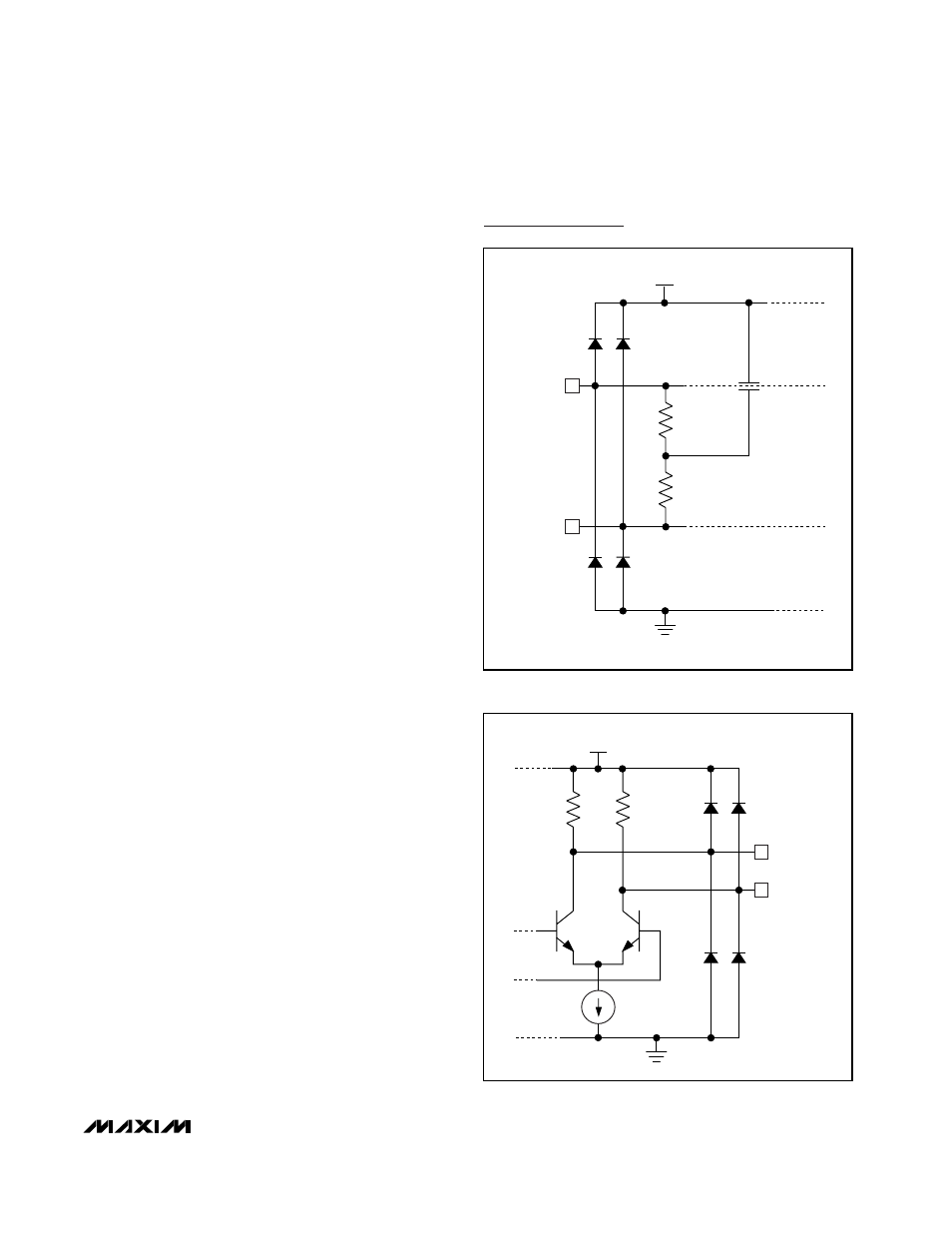
Interface Schematics
MAX3983
Quad Copper-Cable Signal Conditioner
______________________________________________________________________________________
13
RX_IN[1:4]+
TX_IN[1:4]+
GND
50
Ω
50
Ω
RX_IN[1:4]-
TX_IN[1:4]-
5pF
V
CC
X - 1.5V
V
CC
X
Figure 6. RX_IN and TX_IN Equivalent Input Structure
RX_OUT[1:4]+
TX_OUT[1:4]+
GND
50
Ω
50
Ω
RX_OUT[1:4]-
TX_OUT[1:4]-
V
CC
X
Figure 7. RX_OUT and TX_OUT Equivalent Output Structure