Max3983 quad copper-cable signal conditioner, Pin description (continued) – Rainbow Electronics MAX3983 User Manual
Page 10
MAX3983
Quad Copper-Cable Signal Conditioner
10
______________________________________________________________________________________
Pin Description (continued)
PIN
NAME
FUNCTION
55, 58, 61,
64
RX_OUT4+ to
RX_OUT1+
PC Board Transmitter Positive Data Outputs, CML. These outputs are terminated with 50
Ω to V
CC
4.
56, 59, 62,
65
RX_OUT4- to
RX_OUT1-
PC Board Transmitter Negative Data Outputs, CML. These outputs are terminated with 50
Ω to V
CC
4.
67
RX_PE
PC Board Transmitter Preemphasis Control Input, LVTTL with 40k
Ω Internal Pullup. Set high or open
to assert this bit.
68
LOOPBACK
Loopback Enable Input, LVTTL with 40k
Ω Internal Pullup. Set low for normal operation. Set high or
open for internal connection of TX_IN to RX_OUT. TX_OUT continues to transmit when loopback is
enabled.
EP
Exposed Pad
Exposed Pad. Signal and supply ground. For optimal high-frequency performance and thermal
conductivity, this pad must be soldered to the circuit board ground.
TX_OUT[1:4]+
TX_OUT[1:4]-
GND
2
RX_IN[1:4]-
RX_IN[1:4]+
1
0
POR
POWER
MANAGEMENT
LVTTL
LVTTL
SIGNAL
DETECT
LVTTL
CML
PRE-
EMPHASIS
CML
FIXED
EQUALIZER
CML
CML
FIXED
EQUALIZER
PRE-
EMPHASIS
TX_IN[1:4]-
TX_IN[1:4]+
TX_ENABLE
LOOPBACK
TX_PE[0:1]
RX_OUT[1:4]-
RX_OUT[1:4]+
RX_ENABLE
RX_SD[1:4]
RX_PE
40k
Ω
40k
Ω
40k
Ω
TX_SD[1:4]
SIGNAL
DETECT
LIMITER
LIMITER
V
CC
1
V
CC
1
V
CC
3
V
CC
1
V
CC
2
V
CC
2
V
CC
4
LVTTL
LVTTL
40k
Ω
40k
Ω
V
CC
3
V
CC
3
V
CC
4
V
CC
4
V
CC
4
V
CC
3
V
CC
4
V
CC
4
V
CC
2
V
CC
2
V
CC
1
V
CC
3
MAX3983
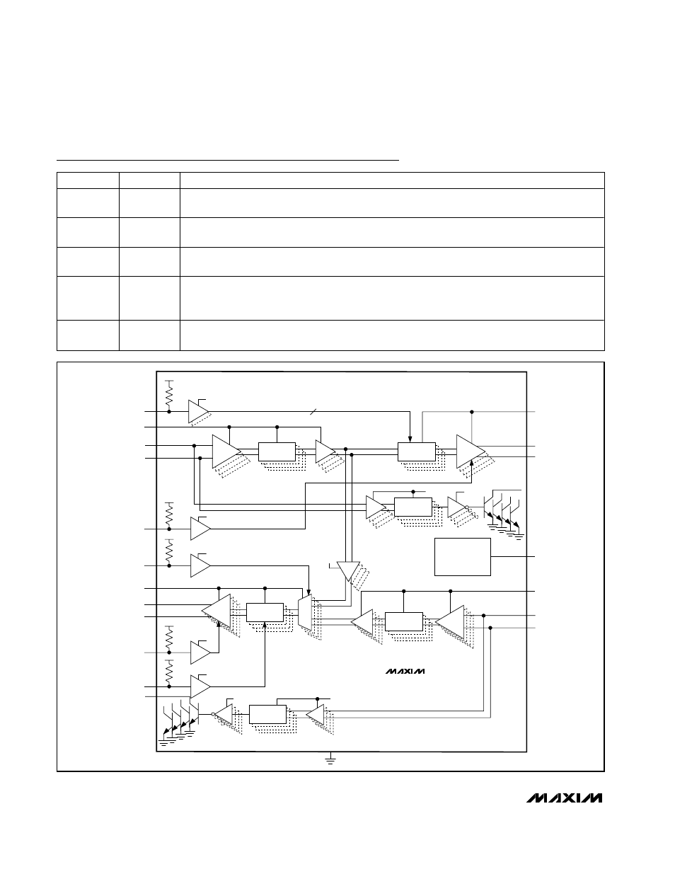
Figure 3. Functional Diagram