Max3983, Quad copper-cable signal conditioner, Applications information – Rainbow Electronics MAX3983 User Manual
Page 12
MAX3983
Applications Information
Signal-Detect Output Leakage Current
Considerations
If all four RX or TX signal-detect outputs are to be con-
nected together to form one signal detect, the leakage
current of the output stage needs to be considered.
Each SD output sinks a maximum of 25µA when assert-
ed, so when four are connected together, a maximum of
100µA is possible. The value of the pullup resistor con-
nected to pullup voltage V
PULLUP
should be selected so
the leakage current does not cause the output voltage to
fall below the threshold of the next stage. For example, if
the signal-detect outputs are connected together and to
a stage with a logic-high threshold of 1.5V, the pullup
resistor needs to be chosen so V
PULLUP
- I
LEAKAGE
x
R
PULLUP
> 1.5V. In this case, if V
PULLUP
= 3.0V,
R
PULLUP
should be less than 15k
Ω.
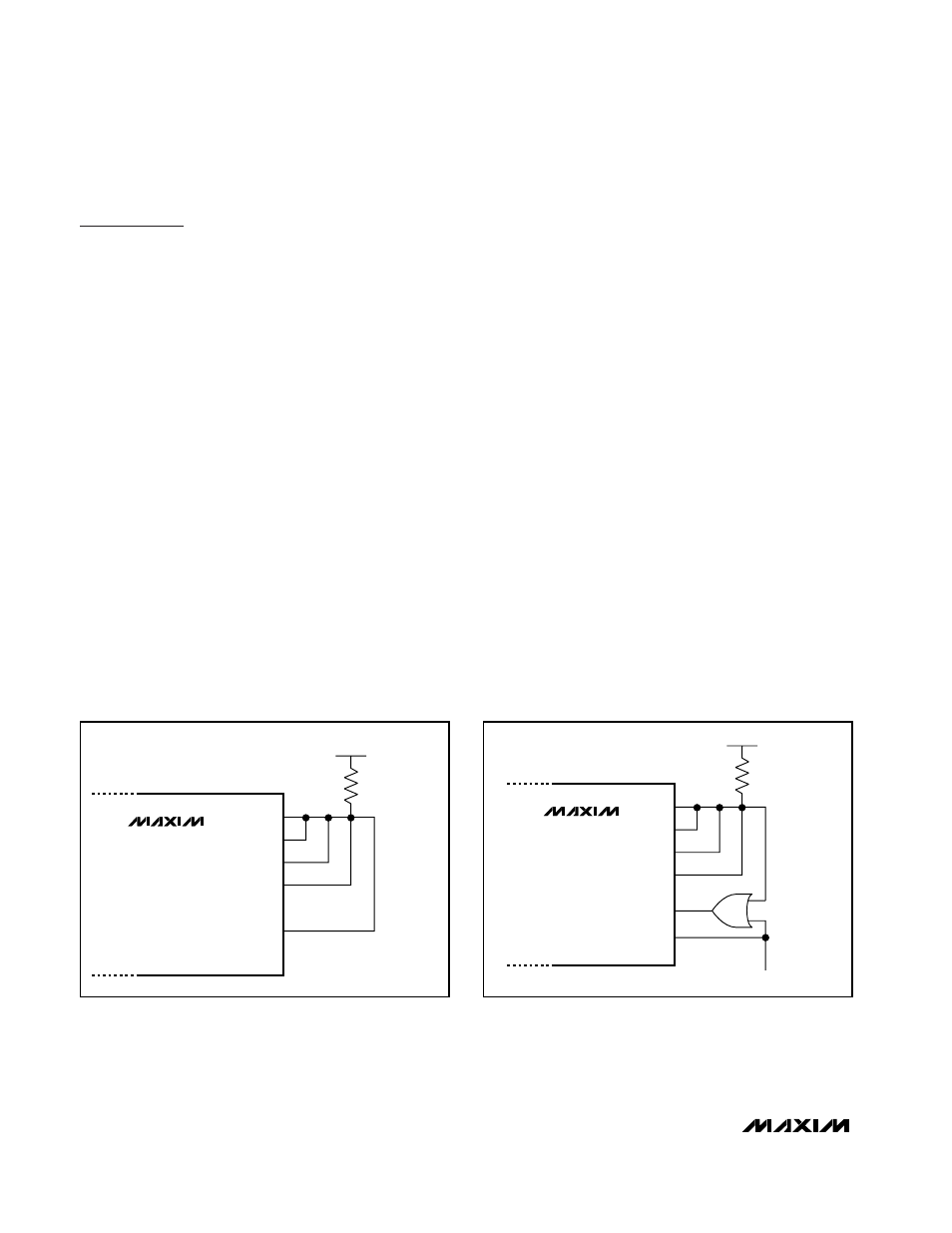
Autodetect
The MAX3983 can automatically detect an incoming sig-
nal and enable the appropriate outputs. Autodetect of
the RX side is done by connecting RX_SD[1:4] together
with a pullup resistor (value 4.7k
Ω to 10kΩ to V
CC
) to
RX_ENABLE. For the TX side, this is done by connecting
TX_SD[1:4] together with a pullup resistor (value 4.7k
Ω
to 10k
Ω to V
CC
) to TX_ENABLE (Figure 4). If signal is
detected on all channels, SD is high and forces the cor-
responding ENABLE high. Leaving the inputs to the
MAX3983 open (i.e., floating) is not recommended, as
noise amplification can occur and create undesirable
output signals. Autodetect is recommended to eliminate
noise amplification or possible oscillation. When using
autodetect, the link length is determined by the received
signal strength. It is possible to reach longer distances if
the autodetect configuration is not used.
Using Loopback with Autodetect
If the MAX3983 is configured for autodetection,
RX_ENABLE is controlled by the RX_SD[1:4] outputs.
Since loopback requires RX_ENABLE to be high, a sim-
ple OR gate can be used to enable the RX outputs
when either RX_SD[1:4] is high or when LOOPBACK is
high (Figure 5).
InfiniBand and 10Gbase-CX4 Transition
Time Specification
InfiniBand specifies a minimum transition time (20% to
80%) of 100ps and CX4 specifies a minimum of 60ps.
Both are specified at the connector interface to the
cable. The output transition times of the MAX3983 are
45ps (typ) and therefore require some care to increase
this time. Approximately 3in of FR4 with 4-mil-wide lines
is sufficient to lengthen the transition time to 60ps. For
100ps transition times, additional length can be used or
an additional 1.5pF capacitor can be placed across the
outputs of the MAX3983. Do not use high-speed dielec-
tric material for the circuit board if the application
requires the use of the InfiniBand or CX4 type connector
system. With such materials, the fast edges of the
Quad Copper-Cable Signal Conditioner
12
______________________________________________________________________________________
MAX3983
RX OR TX_SD1
RX OR TX_SD2
RX OR TX_SD3
RX OR TX_SD4
RX OR TX_ENABLE
3.0V
≤ V
PULLUP
≤ 5.5V
4.7k
Ω ≤ R ≤ 10kΩ
Figure 4. Autodetection Using Corresponding Signal-Detect
Outputs and Enable Input
MAX3983
RX_SD1
RX_SD2
RX_SD3
RX_SD4
RX_ENABLE
LOOPBACK
3.0V
≤ V
PULLUP
≤ 5.5V
4.7k
Ω ≤ R ≤ 10kΩ
TO HOST
Figure 5. Loopback in Autodetect Mode