Max3983 quad copper-cable signal conditioner, Detailed description, Table 1. preemphasis translation – Rainbow Electronics MAX3983 User Manual
Page 11
Detailed Description
The MAX3983 comprises a PC board receiver and
cable driver section (TX), as well as a cable receiver
and PC board driver section (RX). Equalization and sig-
nal detection are provided in each receiver, and pre-
emphasis is included in each transmitter. The MAX3983
includes separate enable control for the TX outputs and
RX outputs. Loopback is provided for diagnostic testing.
PC Board Receiver and Cable Driver
(TX_IN and TX_OUT)
Data is fed into the MAX3983 from the host through a
CML input stage and fixed equalization stage. The
fixed equalizer in the PC board receiver corrects for up
to 20in of PC board loss on FR4 material. The cable dri-
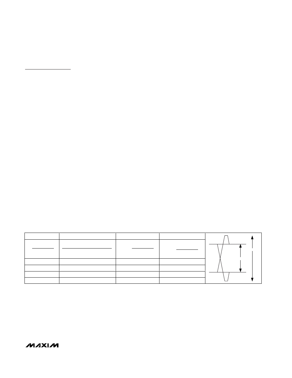
ver includes four-state preemphasis to compensate for
up to 20m of 24AWG, 100
Ω balanced cable. Table 1 is
provided for easy translation between preemphasis
expressions. Residual jitter of the MAX3983 is indepen-
dent of up to 0.17UI
P-P
source jitter.
Cable Receiver and PC Board Driver
(RX_IN and RX_OUT)
The fixed equalizer on each RX input provides approxi-
mately 6dB equalization to correct for up to 5m of
28AWG, 100
Ω balanced cable. The PC board driver
includes two-state preemphasis to compensate for up
to 20in of FR4 material.
Signal-Detect Outputs
Signal detect (SD) is provided on all eight data inputs.
Pullup resistors should be connected from the SD out-
puts to a supply in the 3.0V to 5.5V range. The signal-
detect outputs are not valid until power-up is complete.
Typical signal-detect response time is 0.35µs.
In the RX section, the SD output asserts high when the
RX_IN signal amplitude is greater than 175mV
P-P
.
RX_SD deasserts low when the RX_IN signal amplitude
drops below 85mV
P-P
.
In the TX section, the SD output asserts high when the
TX_IN signal amplitude is greater than 800mV
P-P
.
TX_SD deasserts low when the TX_IN signal amplitude
drops below 200mV
P-P
.
TX and RX Enable
The TX_ENABLE and RX_ENABLE pins enable TX and
RX, respectively. Typical enable time is 15ns, and typi-
cal disable time is 25ns. The enable inputs may be
connected to signal-detect outputs to automatically
detect an incoming signal (see the Autodetect section).
Power-On Reset
To limit inrush current, the MAX3983 includes internal
power-on reset circuitry. Connect a capacitor 0.1µF
≤
C
POR
≤ 10µF from POR to ground. With C
POR
= 1µF,
power-on delay is 6ms (typ).
MAX3983
Quad Copper-Cable Signal Conditioner
______________________________________________________________________________________
11
Table 1. Preemphasis Translation
RATIO
ααα
α
10Gbase-CX4
IN dB
1.41
0.17
0.29
3
2.00
0.33
0.50
6
2.82
0.48
0.65
9
4.00
0.60
0.75
12
V
V
HIGH PP
LOW PP
_
_
V
V
V
V
HIGH PP
LOW PP
HIGH PP
LOW PP
_
_
_
_
−
+
1
_
_
−
V
V
LOW PP
HIGH PP
20 log
_
_
V
V
HIGH PP
LOW PP
V
LOW_PP
V
HIGH_PP