Rainbow Electronics MAX1367 User Manual
Page 17
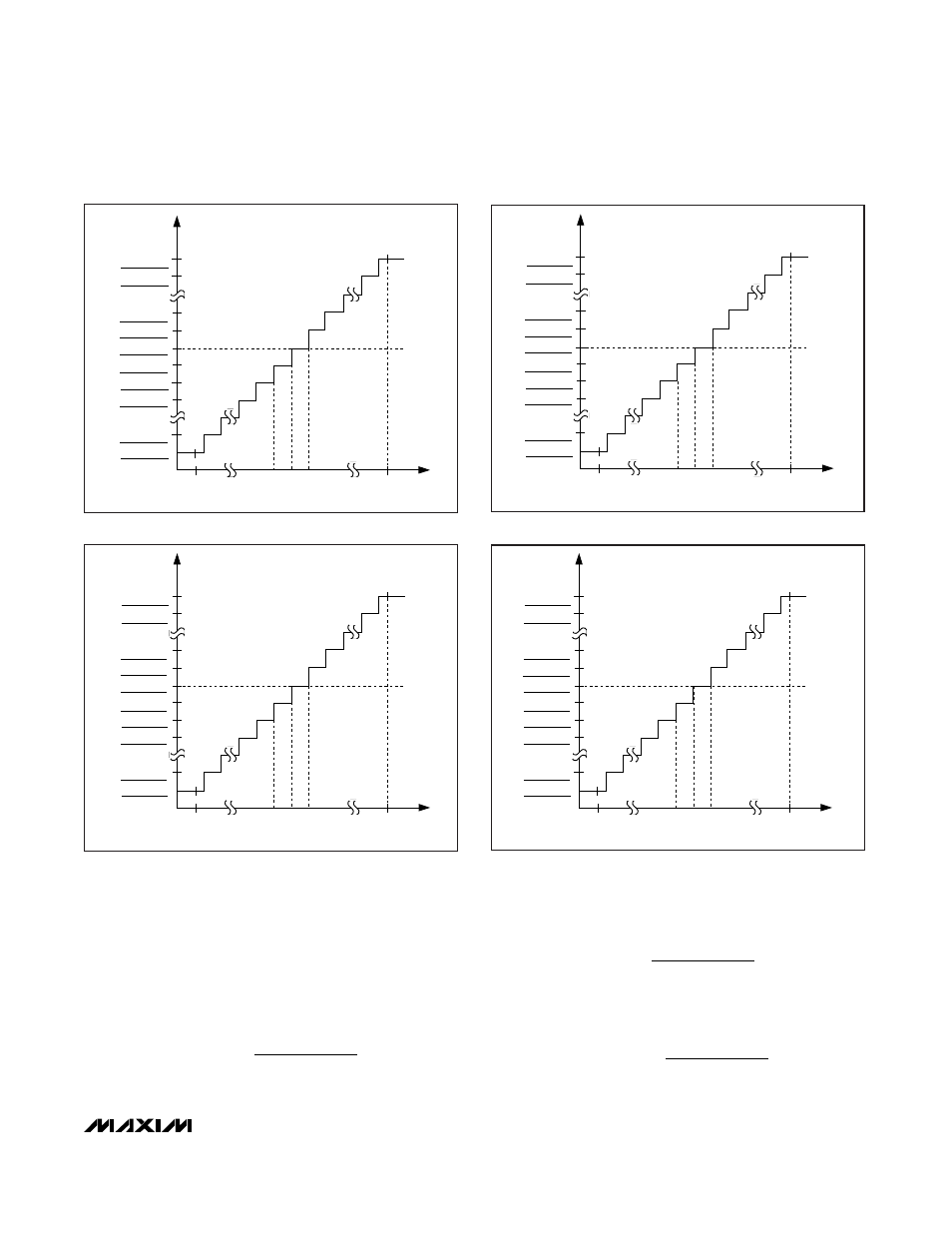
Transfer Functions
ADC Transfer Functions
Figures 7–10 show the transfer functions of the
MAX1365/MAX1367. The output data is stored in the
ADC data register in two’s complement.
The transfer function for the MAX1365 with AIN+ - AIN-
≥ 0 and RANGE = GND is:
The transfer function for the MAX1365 with AIN+ - AIN-
< 0 and RANGE = GND is:
The transfer function for the MAX1367 with AIN+ - AIN-
≥ 0 and RANGE = GND is:
( )
.
3
1 024
2000
COUNT
V
V
V
V
x
AIN
AIN
REF
REF
=
+ −
−
+ −
−
( )
.
,
2
1 024
20 000
1
COUNT
V
V
V
V
x
AIN
AIN
REF
REF
=
+
+ −
−
+ −
−
( )
.
,
1
1 024
20 000
COUNT
V
V
V
V
x
AIN
AIN
REF
REF
=
+ −
−
+ −
−
MAX1365/MAX1367
Stand-Alone, 4.5-/3.5-Digit Panel Meters
with 4–20mA Output
______________________________________________________________________________________
17
-2V
0
ANALOG INPUT VOLTAGE
+2V
LED
1 - - - -
19,999
2
1
0
- 0
- 1
- 2
-19,999
- 1 - - - -
-100
µV 100µV
Figure 7. MAX1365 Transfer Function—±2V Range
-200mV
0
ANALOG INPUT VOLTAGE
+200mV
LED
1 - - - -
19,999
2
1
0
- 0
- 1
- 2
-19,999
- 1 - - - -
-10
µV
10
µV
Figure 8. MAX1365 Transfer Function—±200mV Range
-2V
0
ANALOG INPUT VOLTAGE
+2V
LED
1 - - -
1999
2
1
0
- 0
- 1
- 2
-1999
- 1 - - -
-1mV
1mV
Figure 10. MAX1367 Transfer Function—±2V Range
-200mV
0
ANALOG INPUT VOLTAGE
+200mV
LED
1 - - -
1999
2
1
0
- 0
- 1
- 2
-1999
- 1 - - -
-100
µV 100µV
Figure 9. MAX1367 Transfer Function—±200mV Range