Pin description (continued) – Rainbow Electronics MAX1367 User Manual
Page 10
MAX1365/MAX1367
Stand-Alone, 4.5-/3.5-Digit Panel Meters
with 4–20mA Output
10
______________________________________________________________________________________
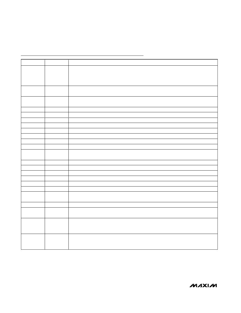
PIN
NAME
FUNCTION
26
HOLD
Hold Logic Input. Connect HOLD to DV
DD
to hold the current ADC value on the LED. Connect
HOLD to GND to update the LED at a rate of 2.5Hz and disable the hold function. Placing the
device into hold mode initiates an offset mismatch calibration. Assert HOLD high for a minimum of
2s to ensure the completion of offset mismatch calibration (see Table 1).
27
DPSET2
Display Decimal-Point Logic-Input 2. Controls the decimal point of the LED. See the Decimal-Point
Control section.
28
DPSET1
Display Decimal-Point Logic-Input 1. Controls the decimal point of the LED. See the Decimal-Point
Control section.
29
LEDG
LED Segment-Drivers Ground
30
DIG0
Digit 0 Driver Out (Connected to GLED for the MAX1367)
31
DIG1
Digit 1 Driver Out
32
DIG2
Digit 2 Driver Out
33
DIG3
Digit 3 Driver Out
34
DIG4
Digit 4 Driver Out
35
SEGA
Segment A Driver
36
SEGB
Segment B Driver
37
LEDV
LED-Display Segment-Driver Supply. Connect to a +2.7V to +5.25V supply. Bypass with a 0.1µF
capacitor to LEDG.
38
SEGC
Segment C Driver
39
SEGD
Segment D Driver
40
SEGE
Segment E Driver
41
SEGF
Segment F Driver
42
SEGG
Segment G Driver
43
SEGDP
Segment DP Driver
44
LED_EN
Active-High LED Enable. The MAX1365/MAX1367 display driver turns off when LED_EN is low.
The MAX1365/MAX1367 LED-display driver turns on when LED_EN is high.
45
NEGV
-2.5V Charge-Pump Voltage Output. Connect a 0.1µF capacitor to GND.
46
DPON
Decimal-Point Enable Input. Controls the decimal point of the LED. See the Decimal-Point Control
section. Connect DPON to DV
DD
to enable the decimal point.
47
REF-
ADC Negative Reference Voltage Input. For internal reference operation, connect REF- to GND.
For external reference operation, bypass REF- to GND with a 0.1µF capacitor and
set V
REF-
from -2.2V to +2.2V (V
REF+
> V
REF-
).
48
REF+
ADC Positive Reference Voltage Input. For internal reference operation, connect a 4.7µF capacitor
from REF+ to GND. For external reference operation, bypass REF+ to GND with a 0.1µF capacitor
and set V
REF+
from -2.2V to +2.2V (V
REF+
> V
REF-
).
Pin Description (continued)