Table 1. led priority table – Rainbow Electronics MAX1367 User Manual
Page 13
The MAX1365/MAX1367 use a multiplexing scheme to
drive one digit at a time. The scan rate is fast enough to
make the digits appear to be lit. Figure 5 shows the
data-timing diagram for the MAX1365/MAX1367 where
T is the display scan period (typically around 1/512Hz
or 1.9531ms). T
ON
in Figure 5 denotes the amount of
time each digit is on and is calculated as follows:
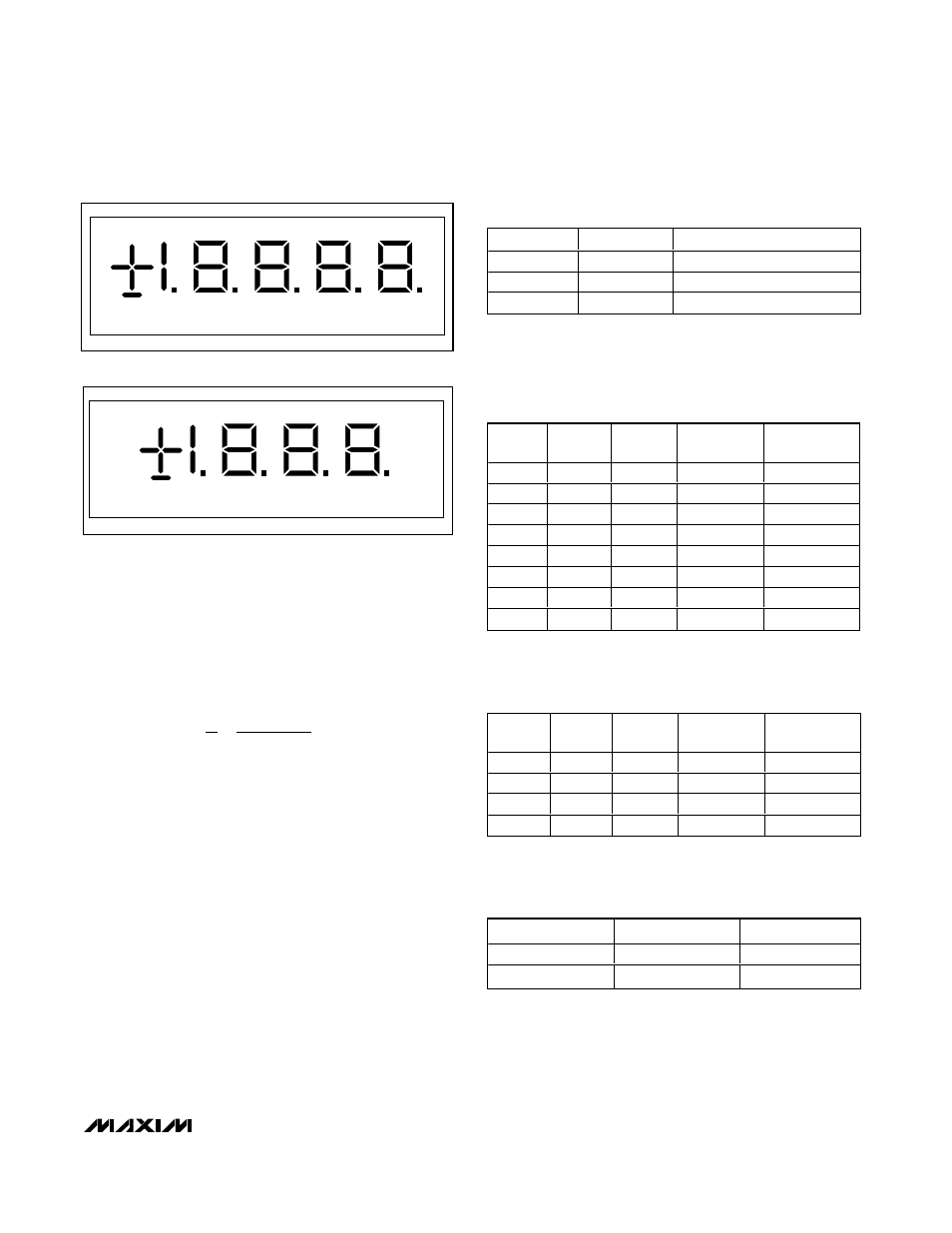
Decimal-Point Control
The MAX1365/MAX1367 allow for full decimal-point
control and feature leading-zero suppression.
Use the DPON, DPSET1, and DPSET2 bits in the con-
trol register to set the value of the decimal point (Tables
2 and 3). The MAX1365/MAX1367 overrange and
underrange display is shown in Table 4.
Leading-Zero Suppression
The MAX1365/MAX1367 include a leading-zero sup-
pression circuitry to turn off unnecessary zeros. For
example, when DPSET1 and DPSET2 = [0,0], 0.0 is dis-
played instead of 000.0 (MAX1365). This feature saves
a substantial amount of power by not lighting unneces-
sary LEDs.
Interdigit Blanking
The MAX1365/MAX1367 also include an interdigit-
blanking circuitry. Without this feature, it is possible to
see a faint digit next to a digit that is completely on.
The interdigit-blanking circuitry prevents ghosting over
into the next digit for a short period of time. The typical
interdigit blanking time is 4µs.
T
T
ms
s
ON
=
=
=
5
1 95312
5
390 60
.
.
µ
MAX1365/MAX1367
Stand-Alone, 4.5-/3.5-Digit Panel Meters
with 4–20mA Output
______________________________________________________________________________________
13
A
B
C
A
A
A
A
D
DIGIT 4
DIGIT 3
DIGIT 2
DIGIT 1
DIGIT 0
D
D
D
D
E
G
F
E
E
E
G
G
G
G
F
F
F
F
B
B
B
B
C
C
C
C
DP
DP
DP
DP
DP
Figure 2. Segment Connection for the MAX1365 (4.5 Digits)
A
B
A
A
A
D
DIGIT 4
DIGIT 3
DIGIT 2
DIGIT 1
D
D
D
E
G
F
E
E
G
G
G
F
F
F
B
B
B
C
C
C
DP
DP
DP
DP
C
Figure 3. Segment Connection for the MAX1367 (3.5 Digits)
HOLD
PEAK
DISPLAY VALUES FORM
1
X
Hold value
0
1
Peak value
0
0
Latest ADC result
Table 1. LED Priority Table
X = Don’t care.
DPON
DPSET1
DPSET2
DISPLAY
OUTPUT
ZERO INPUT
READING
1
0
0
1888.
0.
1
0
1
188.8
0.0
1
1
0
18.88
0.00
1
1
1
1.888
0.000
Table 3. Decimal-Point Control Table—
MAX1367
CONDITION
MAX1367
MAX1365
Overrange
1---
1----
Underrange
-1---
-1----
Table 4. LED During Overrange and
Underrange Conditions
DPON
DPSET1
DPSET2
DISPLAY
OUTPUT
ZERO INPUT
READING
0
0
0
18888
0
0
0
1
18888
0
0
1
0
18888
0
0
1
1
18888
0
1
0
0
1888.8
0.0
1
0
1
188.88
0.00
1
1
0
18.888
0.000
1
1
1
1.8888
0.0000
Table 2. Decimal-Point Control Table—
MAX1365