Applications information, Table 5. current output table – Rainbow Electronics MAX1367 User Manual
Page 15
Bipolar Mode
Set EN_BPM high to engage bipolar operation. In bipo-
lar mode, the current output at 4–20OUT (4–20mA or
0 to 16mA) maps the analog input voltage (±2V or
±200mV). In bipolar mode, a 0V analog input maps to
midscale (12mA). See Table 5 for current output (see
Figures 12 and 13).
5.2V Linear Regulator with Compensation
The MAX1365/MAX1367 feature a 5.2V linear regulator.
The 5.2V regulator consists of an op amp and connec-
tions to an external depletion-mode FET. The 5.2V regu-
lator regulates the loop voltage that powers the
voltage-to-current converter and the rest of the trans-
mitter circuitry. The regulator output voltage is available
at REG_VDD and is given by the equation:
V
REG_VDD
= 2.54 x V
REF+
The FET breakdown and saturation voltages determine
the usable range of loop voltages (V
EXT
). The external
FET parameters such as V
GS
(off), I
DSS
, and transcon-
ductance must be chosen so that the op amp output on
the REG_FORCE pin can control the FET operating
point while swinging in the range from VREG_AMP to
REG_VDD. See the Selecting Depletion-Mode FET sec-
tion in the Applications Information section.
Connect a 0.1µF capacitor between CMP and
REG_FORCE to ensure stable operation of the regulator.
Applications Information
Power-On Reset
At power-on, the digital filter and modulator circuits
reset. The MAX1365 allows 6s for the reference to sta-
bilize before performing enhanced offset calibration.
MAX1365/MAX1367
Stand-Alone, 4.5-/3.5-Digit Panel Meters
with 4–20mA Output
______________________________________________________________________________________
15
CURRENT OUTPUT (mA)
ANALOG INPUT
UNIPOLAR MODE
(EN_I = LOW)
UNIPOLAR MODE
(EN_I = HIGH)
BIPOLAR MODE
(EN_I = LOW)
BIPOLAR MODE
(EN_I = HIGH)
Negative Full Scale
0
4
0
4
0V
0
4
8
12
Positive Full Scale
16
20
16
20
Table 5. Current Output Table
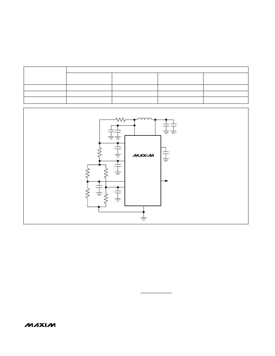
MAX1365
MAX1367
AV
DD
DV
DD
10
µF
10
µF
0.1
µF
0.1
µF
0.1
µF
0.1
µF
ANALOG SUPPLY
FERRITE
BEAD
R
REF
R
R
ACTIVE
GAUGE
DUMMY
GAUGE
REF+
REF-
NEGV
AIN+
AIN-
4-20OUT
4–20mA/0 TO 16mA
CURRENT-LOOP
OUTPUT
GND
0.1
µF
0.1
µF
Figure 6. Strain-Gauge Application with the MAX1365/MAX1367