Detailed description, Functional diagram, Analog input protection – Rainbow Electronics MAX1367 User Manual
Page 11: Internal analog input/reference buffers, Modulator
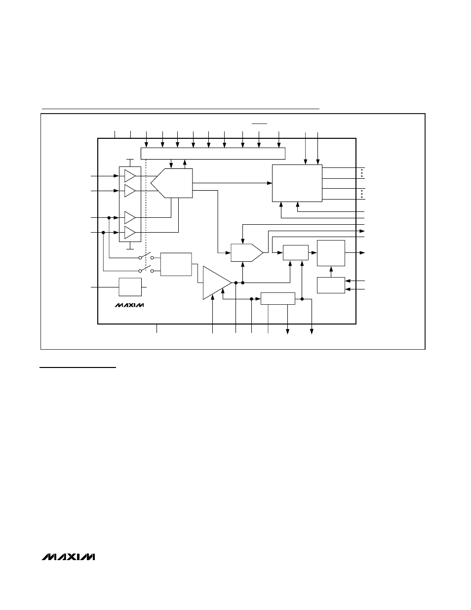
Detailed Description
The MAX1365/MAX1367 low-power, highly integrated
ADCs with LED drivers convert a ±2V differential input
voltage (one count is equal to 100µV for the MAX1365
and 1mV for the MAX1367) with a sigma-delta ADC and
output the result to an LED display. An additional
±200mV input range (one count is equal to 10µV for the
MAX1365 and 100µV for the MAX1367) is available to
measure small signals with finer resolution.
In addition to displaying the results on an LED display,
these devices feature a DAC and V-to-I converter for
4–20mA (or 0 to 16mA) current output that proportional-
ly follows the ADC input. The MAX1365/MAX1367 use
an external depletion-mode NMOS transistor to regulate
7V to 30V for the V/I converter. Use the 4–20mA (or 0 to
16mA) output to drive a remote display, data logger,
PLC input, or other 4–20mA devices in a current loop.
The MAX1365/MAX1367 include a 2.048V reference,
internal charge pump, and a high-accuracy on-chip
oscillator. The devices feature on-chip buffers for the dif-
ferential input signal and external-reference inputs,
allowing direct interface with high-impedance signal
sources. In addition, they use continuous internal offset-
calibration and offer > 100dB of 50Hz and 60Hz line-
noise rejection. Other features include data hold and
peak detection and overrange/underrange detection.
Analog Input Protection
The MAX1365/MAX1367 provide internal protection
diodes that limit the analog input range on AIN+, AIN-,
REF+, and REF- from NEGV to (AV
DD
+ 0.3V). If the
analog input exceeds this range, limit the input current
to 10mA.
Internal Analog Input/Reference Buffers
The MAX1365/MAX1367 analog input/reference buffers
allow the use of high-impedance signal sources. The
input buffers’ common-mode input range allows the ana-
log inputs and the reference to range from -2.2V to +2.2V.
Modulator
The MAX1365/MAX1367 perform analog-to-digital con-
versions using a single-bit, 3rd-order, sigma-delta mod-
ulator. The sigma-delta modulator converts the input
MAX1365/MAX1367
Stand-Alone, 4.5-/3.5-Digit Panel Meters
with 4–20mA Output
______________________________________________________________________________________
11
LED
DRIVER
LEDG
SEGA
SEGG
DIG0(1)
DIG4(4)
LED_EN
MAX1365
MAX1367
ADC
INPUT
BUFFER
-2.5V
AIN+
AIN-
REF+
REF-
NEGV
+2.5V
2.048V
BANDGAP
REFERENCE
LOGIC
GND
CHARGE
PUMP
-2.5V
OUTPUT
DAC
DAC REF
BUFFER
AV
DD
DV
DD
RANGE
INTREF
5V REGULATOR
V/I
CONVERTER
CURRENT
SUMMER
AND
AMPLIFIER
OFFSET
GENERATOR
EN_BPM
EN_I
DACVOUT
4-20OUT
REG_FORCE
DACDATA_SEL
SET
CS_DAC
REFSELE
REG_AMP
REF_DAC
CONV_IN
CMP
REG_VDD
DAC_VDD
LEDV
DPON DPSET1 DPSET 2
PEAK
HOLD
Functional Diagram