Pin description – Rainbow Electronics MAX552 User Manual
Page 7
MAX551/MAX552
+3V/+5V, 12-Bit, Serial, Multiplying DACs
in 10-Pin µMAX Package
_______________________________________________________________________________________
7
______________________________________________________________Pin Description
PIN
NAME
1
1
OUT
—
2
AGND
2
3
GND
6
7
SCLK
5
6
DIN
4
5
LOAD
3
4
V
DD
8
10
RFB
7
9
REF
—
8
CLR
Feedback Resistor
Reference Input
Clear DAC Input. Clears the DAC register. Tie to V
DD
or float if not used.
Serial-Clock Input. The serial input data is clocked in on SCLK’s rising edge.
Serial-Data Input
Active-Low Load DAC Input. Driving this asynchronous input low transfers the contents
of the input register to the DAC register.
Supply Voltage
Digital Ground. Also Analog Ground for DIP package.
Analog Ground
DAC Current Output
FUNCTION
µMAX
DIP
D1
D9
2R
R
R
R
R
2R
2R
2R
2R
2R
AGND
OUT
V
REF
R
FB
*
R
FB
* = R
RFB
D10
D11
(MSB)
DO
(LSB)
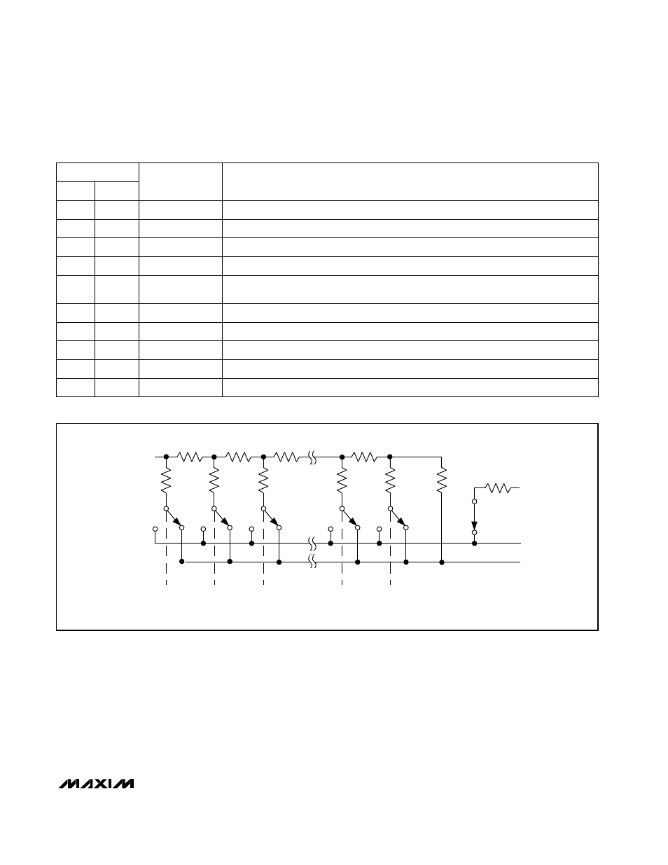
Figure 1. MAX551/MAX552 Simplified Circuit