Max1471, Data filters – Rainbow Electronics MAX1471 User Manual
Page 12
MAX1471
Data Filters
The data filters for the ASK and FSK data are imple-
mented as a 2nd-order lowpass Sallen-Key filter. The
pole locations are set by the combination of two on-
chip resistors and two external capacitors. Adjusting
the value of the external capacitors changes the corner
frequency to optimize for different data rates. The cor-
ner frequency in kHz should be set to approximately
1.5 times the fastest expected Manchester data rate in
kbps from the transmitter. Keeping the corner frequen-
cy near the data rate rejects any noise at higher fre-
quencies, resulting in an increase in receiver sensitivity.
The configuration shown in Figure 3 can create a
Butterworth or Bessel response. The Butterworth filter
offers a very flat amplitude response in the passband
and a rolloff rate of 40dB/decade for the two-pole filter.
The Bessel filter has a linear phase response, which
works well for filtering digital data. To calculate the
value of the capacitors, use the following equations,
along with the coefficients in Table 2:
where f
C
is the desired 3dB corner frequency.
For example, choose a Butterworth filter response with
a corner frequency of 5kHz:
C
b
a
k
f
C
a
k
f
F1
C
F2
C
=
(
)( )( )
=
(
)( )( )
100
4 100
π
π
315MHz/434MHz Low-Power, 3V/5V
ASK/FSK Superheterodyne Receiver
12
______________________________________________________________________________________
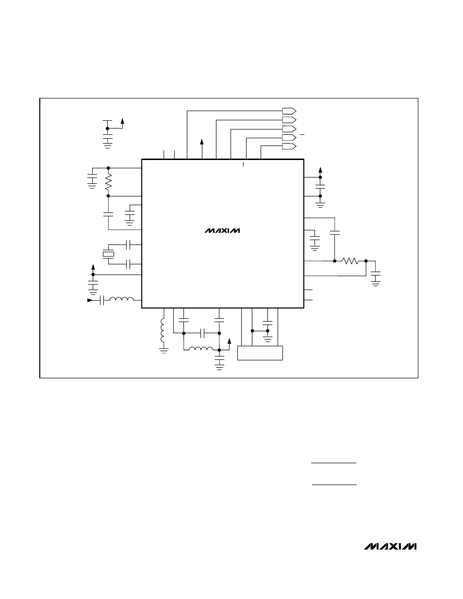
Figure 2. Typical Application Circuit
ASK DATA OUT
SCLK
DIO
FSK DATA OUT
MAX1471
V
CC
IN GND
Y2
OUT
CS
DFF
22
DSF-
19
PDMAXF
18
PDMINF
17
PDMAXA
32
PDMINA
31
ADATA
30
HV
IN
29
SLCK
28
DIO
27
26
FDATA
25
DSA+
2
LNASRC
9
LNAOUT
10
MIXOUT
13
AGND
14
IFIN+
16
CS
DV
DD
24
DGND
23
C23
V
DD
OPF+
21
C21
C22
R8
C27
DSF+
20
V
DD
OPA+
3
C3
OPF+
21
C21
DSA-
1
C5
DFA
4
R3
C4
XTAL2
5
C14
XTAL1
6
C15
AV
DD
7
C6
V
DD
C7
LNAIN
8
RF INPUT
Y1
C9
L3
MIXIN-
12
C10
C8
IFIN-
15
C12
MIXIN+
11
C11
V
DD
L2
L1
C26
3.0V
V
DD