Typical operating characteristics, Electrical characteristics (continued) – Rainbow Electronics MAX1821 User Manual
Page 5
MAX1820/MAX1821
WCDMA Cellular Phone 600mA
Buck Regulators
_______________________________________________________________________________________
5
Note 2: Limits are 100% production tested at T
A
= +25°C for UCSP parts. Limits over the entire operating temperature range are
guaranteed by design and characterization but are not production tested.
Note 3: Specifications to -40°C are guaranteed by design and not subject to production test.
PARAMETER
SYMBOL
CONDITIONS
MIN
MAX
UNITS
LX Leakage Current
I
LX
V
BATT
= 5.5V, LX = GND or BATT
-1
1
µA
Maximum Duty Cycle
duty
MAX
100
%
SKIP = GND
0
Minimum Duty Cycle
duty
MIN
SKIP = BATT, V
BATT
= 4.2V
10
%
SYNC AND OSCILLATOR
S Y N C = si ne w ave, S Y N C i np ut = 200m V
P-P
13
13
SYNC Divide Ratio
(MAX1820X)
S Y N C = si ne w ave, S Y N C i np ut = 800m V
P-P
13
13
Hz/Hz
SYNC Capture Range
(MAX1820X)
SYNC = sine wave, AC-coupled,
SYNC input = 500mV
P-P
10
16
MHz
S Y N C = si ne w ave, S Y N C i np ut = 200m V
P-P
18
18
SYNC Divide Ratio
(MAX1820Y)
S Y N C = si ne w ave, S Y N C i np ut = 800m V
P-P
18
18
Hz/Hz
SYNC Capture Range
(MAX1820Y)
SYNC = sine wave, AC-coupled,
SYNC input = 500mV
P-P
15
21
MHz
V
SYNC
= IV ( M AX 1820Z , M AX 1821) -1
+1
SYNC Leakage Current
I
SYNC
V
SYNC
= IV ( M AX 1820X , M AX 1820Y , and
M AX 1821X )
-5
+5
µA
Internal Oscillator Frequency
(MAX1820Z, MAX1821)
f
OSC
SYNC = GND
0.8
1.2
MHz
LOGIC INPUTS (SKIP, SHDN)
Logic Input High
V
IH
1.6
V
Logic Input Low
V
IL
0.4
V
Logic Input Current
1
µA
ELECTRICAL CHARACTERISTICS (continued)
(V
BATT
= 3.6V, SHDN = BATT, SKIP = SYNC = GND, V
REF
= 1.25V (MAX1820 only), T
A
= -40°C to +85°C, unless otherwise noted.)
(Notes 2, 3)
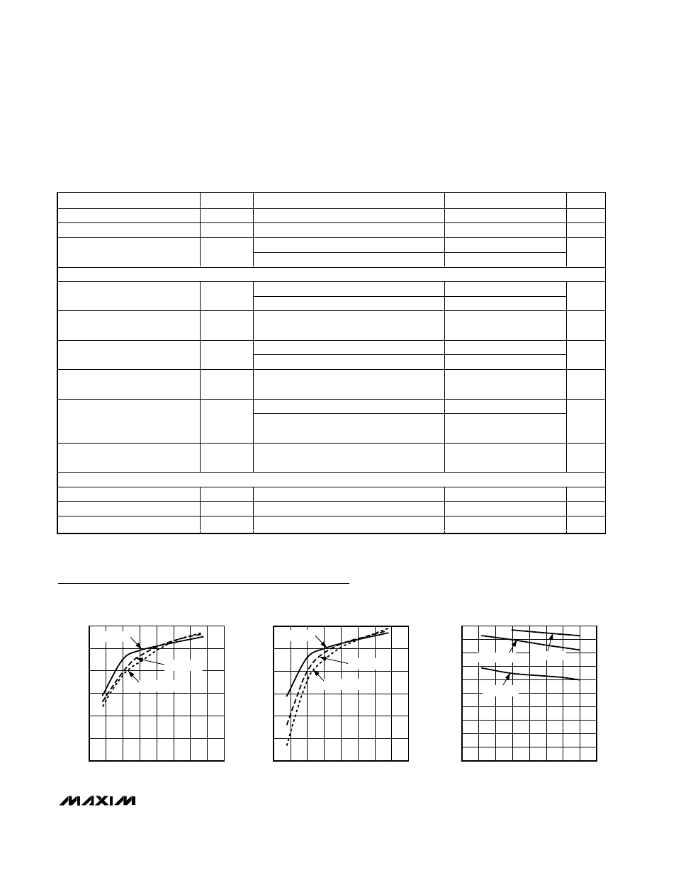
40
50
60
70
80
90
100
0
1.0
0.5
1.5
2.0
2.5
3.0
3.5
4.0
EFFICIENCY vs. OUTPUT VOLTAGE
(NORMAL MODE, V
IN
= 3.6V)
MAX1820/21 toc01
OUTPUT VOLTAGE (V)
EFFICIENCY (%)
R
LOAD
= 10
Ω
R
LOAD
= 15
Ω
R
LOAD
= 5
Ω
40
50
60
70
80
90
100
0
1.0
0.5
1.5
2.0
2.5
3.0
3.5
4.0
EFFICIENCY vs. OUTPUT VOLTAGE
(PWM MODE, V
IN
= 3.6V)
MAX1820/21 toc02
OUTPUT VOLTAGE (V)
EFFICIENCY (%)
R
LOAD
= 10
Ω
R
LOAD
= 15
Ω
R
LOAD
= 5
Ω
0
20
10
40
30
60
50
70
90
80
100
2.0
3.0
3.5
2.5
4.0
4.5
5.0
5.5
6.0
MAX1820/21 toc03
V
IN
(V)
EFFICIENCY (%)
EFFICIENCY vs. INPUT VOLTAGE
NORMAL MODE, R
LOAD
= 10
Ω
V
OUT
= 1.8V
V
OUT
= 3.4V
V
OUT
= 0.4V
Typical Operating Characteristics
(T
A
= +25°C, unless otherwise noted.)