Table 1. suggested inductors – Rainbow Electronics MAX1821 User Manual
Page 14
MAX1820/MAX1821
WCDMA Cellular Phone 600mA
Buck Regulators
14
______________________________________________________________________________________
3) Calculate the equivalent load impedance, R
L
, by:
4) Calculate the compensation resistance (R
C
) value to
cancel out the dominant pole created by the output
load and the output capacitance:
Solving for R
C
gives:
5) Calculate the high-frequency compensation pole to
cancel the zero created by the output capacitor’s
equivalent series resistance (ESR):
Solving for C2 gives:
In this case, C2 can be omitted due to the use of
ceramic capacitors. Larger output capacitors and high-
er ESR may require the use of capacitor C2.
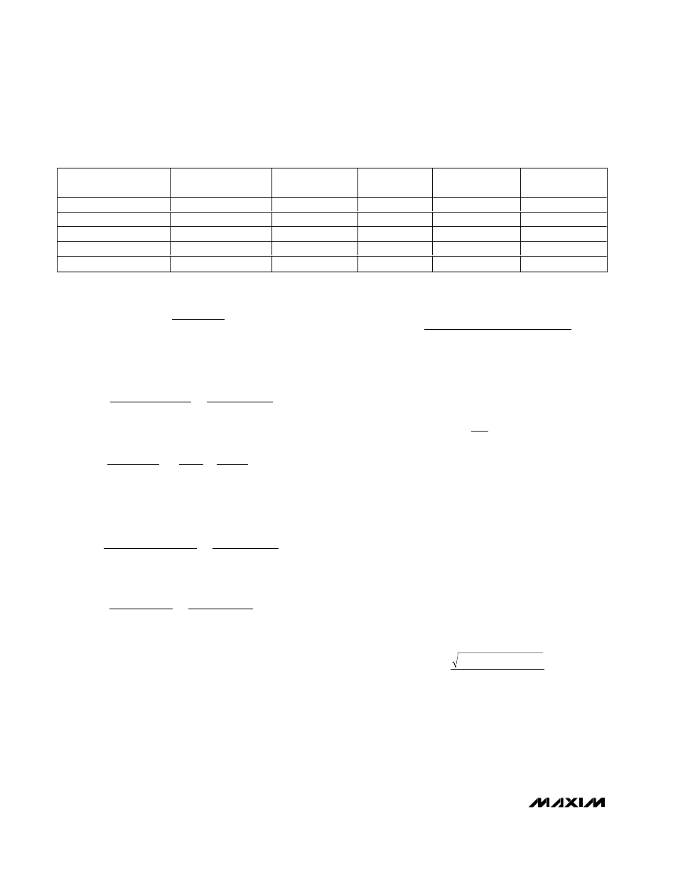
Inductor Selection
A 4µH to 6µH inductor with a saturation current of at
least 800mA is recommended for most applications.
For best efficiency, the inductor’s DC resistance should
be <200m
Ω, and saturation current should be >1A. See
Table 1 for recommended inductors and manufacturers.
For most designs, a reasonable inductor value (L
IDEAL
)
can be derived from the following equation:
where LIR is the inductor current ripple as a percentage.
LIR should be kept between 20% and 40% of the maxi-
mum load current for best performance and stability.
The maximum inductor current is:
The inductor current becomes discontinuous if I
OUT
decreases to LIR/2 from the output current value used
to determine L
IDEAL
.
Input Capacitor Selection
The input capacitor reduces the current peaks drawn
from the battery or input power source and reduces
switching noise in the IC. The impedance of the input
capacitor at the switching frequency should be less
than that of the input source so high-frequency switch-
ing currents do not pass through the input source.
The input capacitor must meet the ripple-current
requirement (I
RMS
) imposed by the switching currents.
Nontantalum chemistries (ceramic, POSCAP, or OS-
CON) are preferred due to their resistance to power-up
surge currents:
For optimal circuit reliability, choose a capacitor that
has less than 10°C temperature rise at the peak ripple
current.
I
V
(V
- V
)
V
RMS
LOAD
OUT
BATT
OUT
BATT
=
I
I
I
L(MAX)
OUT(MAX)
= +
1
2
LIR
L
V
(V
- V
)
V
IDEAL
OUT
BATT
OUT
BATT
OUT(MAX)
OSC
=
Ч
Ч
Ч ƒ
LIR I
C
R
C
R
k
pF
2
3
0 01
80 8
0 55
=
Ч
=
Ч
=
ESR
OUT
4.7 F
µ
.
.
.
Ω
Ω
1
2
1
2
ESR
OUT
Ч Ч
Ч
=
Ч Ч
Ч
π
π
R
C
R
C
3
2
`
RC
R
C1
3.4V
0.6A
4.7
= 80.8k
L
OUT
=
×
=
C
F
pF
µ
330
Ω
1
2
1
2
L
OUT
C
Ч Ч
Ч
=
Ч Ч
Ч
π
π
R
C
R
C1
RL
V
I
OUT(MAX)
OUT(MAX)
≈
Table 1. Suggested Inductors
MANUFACTURER
PART NUMBER
INDUCTANCE
(µH)
ESR (m
Ω)
SATURATION
CURRENT (A)
DIMENSIONS
(mm)
Coilcraft
DO1606
4.7
120
1.2
5.3
✕
5.3
✕
2.0
Coilcraft
LPT1606-472
4.7
240 (max)
1.2
6.5
✕
5.3
✕
2.0
Sumida
CDRH4D18-4R7
4.7
125
0.84
5
✕
5
✕
2
Sumida
CR43
4.7
108.7
1.15
4.5
✕
4.0
✕
3.5
Sumida
CDRH5D18-4R1
4.1
57
1.95
5.5
✕
5.5
✕
2.0