Pin description – Rainbow Electronics MAX1181 User Manual
Page 9
MAX1181
Dual 10-Bit, 80Msps, +3V, Low-Power ADC with
Internal Reference and Parallel Outputs
_______________________________________________________________________________________
9
Pin Description
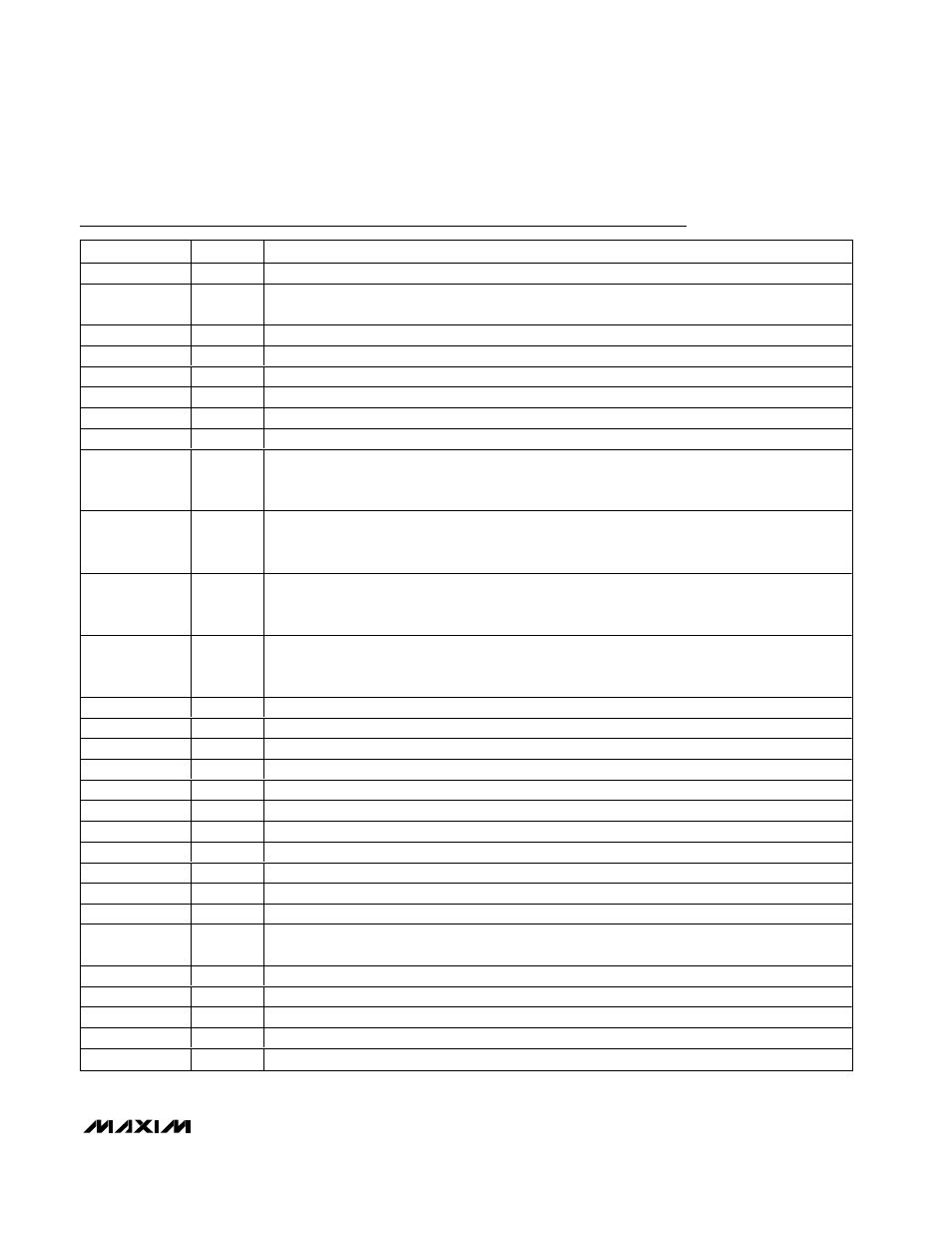
PIN
NAME
FUNCTION
1
COM
Common-Mode Voltage Input/Output. Bypass to GND with a
≥0.1µF capacitor.
2, 6, 11, 14, 15
V
DD
Analog Supply Voltage. Bypass to GND with a capacitor combination of 2.2µF in parallel with
0.1µF.
3, 7, 10, 13, 16
GND
Analog Ground
4
INA+
Channel ‘A’ Positive Analog Input. For single-ended operation, connect signal source to INA+.
5
INA-
Channel ‘A’ Negative Analog Input. For single-ended operation, connect INA- to COM.
8
INB-
Channel ‘B’ Negative Analog Input. For single-ended operation, connect INB- to COM.
9
INB+
Channel ‘B’ Positive Analog Input. For single-ended operation, connect signal source to INB+.
12
CLK
Converter Clock Input
17
T/B
T/B selects the ADC digital output format.
High: Two’s complement.
Low: Straight offset binary.
18
SLEEP
Sleep Mode Input.
High: Deactivates the two ADCs, but leaves the reference bias circuit active.
Low: Normal operation.
19
PD
Power-Down Input.
High: Power-down mode.
Low: Normal operation.
20
OE
Output Enable Input.
High: Digital outputs disabled.
Low: Digital outputs enabled.
21
D9B
Three-State Digital Output, Bit 9 (MSB), Channel B
22
D8B
Three-State Digital Output, Bit 8, Channel B
23
D7B
Three-State Digital Output, Bit 7, Channel B
24
D6B
Three-State Digital Output, Bit 6, Channel B
25
D5B
Three-State Digital Output, Bit 5, Channel B
26
D4B
Three-State Digital Output, Bit 4, Channel B
27
D3B
Three-State Digital Output, Bit 3, Channel B
28
D2B
Three-State Digital Output, Bit 2, Channel B
29
D1B
Three-State Digital Output, Bit 1, Channel B
30
D0B
Three-State Digital Output, Bit 0 (LSB), Channel B
31, 34
OGND
Output Driver Ground
32, 33
OV
DD
Output Driver Supply Voltage. Bypass to OGND with a capacitor combination of 2.2µF in parallel
with 0.1µF.
35
D0A
Three-State Digital Output, Bit 0 (LSB), Channel A
36
D1A
Three-State Digital Output, Bit 1, Channel A
37
D2A
Three-State Digital Output, Bit 2, Channel A
38
D3A
Three-State Digital Output, Bit 3, Channel A
39
D4A
Three-State Digital Output, Bit 4, Channel A