Functional diagram, Chip information – Rainbow Electronics MAX1181 User Manual
Page 18
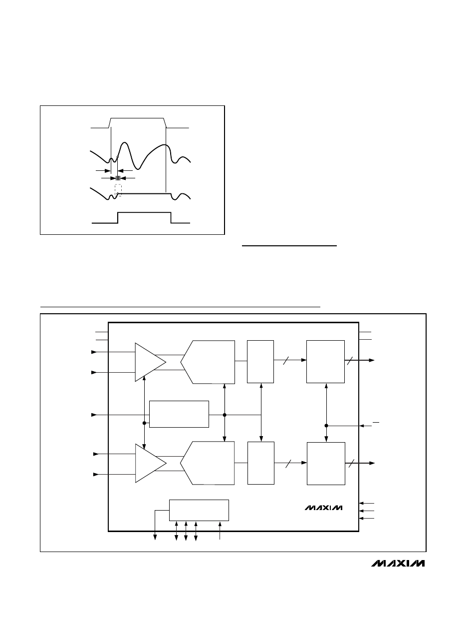
MAX1181
Dual 10-Bit, 80Msps, +3V, Low-Power ADC with
Internal Reference and Parallel Outputs
18
______________________________________________________________________________________
GND
REFERENCE
OUTPUT
DRIVERS
CONTROL
T/H
T/H
PIPELINE
ADC
DEC
OUTPUT
DRIVERS
REFOUT
REFN COM REFP
REFIN
INA+
INA-
CLK
INB+
INB-
V
DD
DEC
PIPELINE
ADC
OGND
OV
DD
D9A–D0A
OE
D9B–D0B
T/B
PD
SLEEP
MAX1181
10
10
10
10
Functional Diagram
where V
1
is the fundamental amplitude, and V
2
through
V
5
are the amplitudes of the 2nd- through 5th-order
harmonics.
Spurious-Free Dynamic Range (SFDR)
SFDR is the ratio expressed in decibels of the RMS
amplitude of the fundamental (maximum signal compo-
nent) to the RMS value of the next largest spurious
component, excluding DC offset.
Intermodulation Distortion (IMD)
The two-tone IMD is the ratio expressed in decibels of
either input tone to the worst 3rd-order (or higher) inter-
modulation products. The individual input tone levels
are at -6.5dB full scale and their envelope is at -0.5dB
full scale.
Chip Information
TRANSISTOR COUNT: 10,811
PROCESS: CMOS
HOLD
ANALOG
INPUT
SAMPLED
DATA (T/H)
T/H
t
AD
t
AJ
TRACK
TRACK
CLK
Figure 9. T/H Aperture Timing