Rainbow Electronics MAX3673 User Manual
Page 2
MAX3673
Low-Jitter Frequency Synthesizer
with Selectable Input Reference
2
_______________________________________________________________________________________
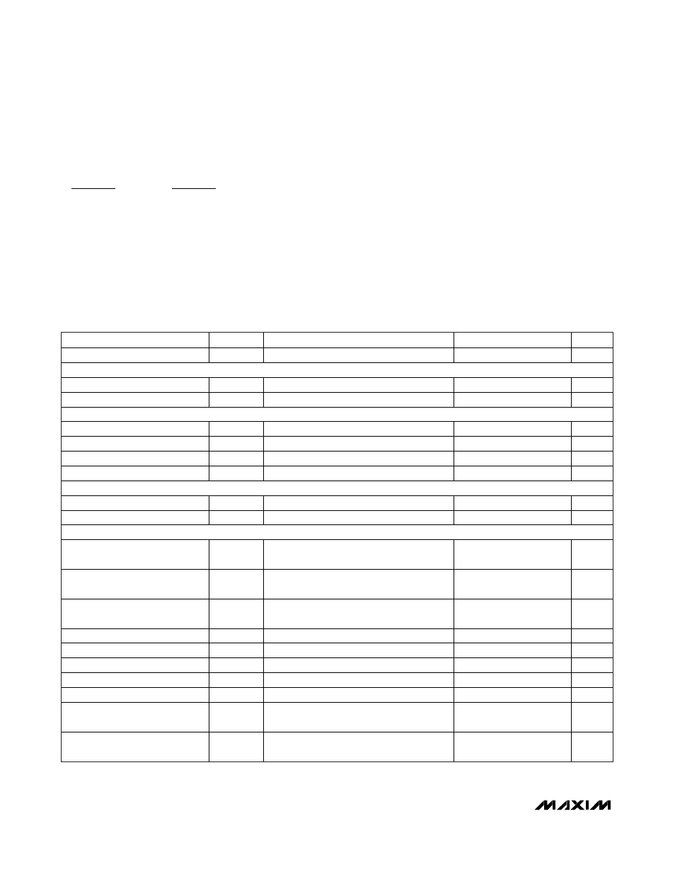
ABSOLUTE MAXIMUM RATINGS
ELECTRICAL CHARACTERISTICS
(V
CC
= +3.0V to +3.6V, T
A
= -40°C to +85°C, C
PLL
= 0.1µF, C
REG
= 0.22µF. Typical values are at V
CC
= +3.3V, T
A
= +25°C, unless
otherwise noted.)
Stresses beyond those listed under “Absolute Maximum Ratings” may cause permanent damage to the device. These are stress ratings only, and functional
operation of the device at these or any other conditions beyond those indicated in the operational sections of the specifications is not implied. Exposure to
absolute maximum rating conditions for extended periods may affect device reliability.
Supply Voltage Range (V
CC
, VCC_VCO)..............-0.3V to +4.0V
LVPECL Output Current (OUTA[3:0],
, OUTB[4:0],
) .............................-56mA
All Other Pins..............................................-0.3V to (V
CC
+ 0.3V)
Continuous Power Dissipation (T
A
= +70
°C)
56-Pin TQFN (derate 47.6mW/
°C above 70°C)..........3808mW
Operating Junction Temperature (T
J
)................-55
°C to +150°C
Storage Temperature Range .............................-65
°C to +160°C
Lead Temperature (soldering, 10s) .................................+300
°C
OUTB[ : ]
4 0
OUTA[ : ]
3 0
PARAMETER
SYMBOL
CONDITIONS
MIN
TYP
MAX
UNITS
Supply Current
I
CC
LVPECL
outputs
unterminated
120 175 mA
POWER-ON RESET
V
CC
Rising
(Note 1)
2.55
V
V
CC
Falling
(Note 1)
2.45
V
LVCMOS/LVTTL INPUTS (
MR, SEL_CLK, PLL_BYPASS, FB_SEL)
Input High Voltage
V
IH
2.0
V
Input Low Voltage
V
IL
0.8 V
Input High Current
I
IH
V
IN
= V
CC
75
μA
Input Low Current
I
IL
V
IN
= GND
-75
μA
LVCMOS/LVTTL OUTPUTS (
IN0FAIL, IN1FAIL, LOCK)
Output High Voltage
V
OH
I
OH
= -8mA
2.4
V
Output Low Voltage
V
OL
I
OL
= +8mA
0.4
V
LVPECL INPUTS (REFCLK0,
REFCLK0, REFCLK1, REFCLK1, FB_IN, FB_IN) (Note 2)
Input High Voltage
V
IH
V
CC
-
0.7
V
Input Low Voltage
V
IL
V
CC
-
2.0
V
Input Bias Voltage
V
CMI
V
CC
-
1.8
V
CC
-
1.34
V
Differential-Input Swing
0.15
1.9
V
P-P
Differential-Input Impedance
> 40
k
Common-Mode Input Impedance
> 14
k
Input Capacitance
1.5
pF
Input Current
V
IH
= V
CC
- 0.7V, V
IL
= V
CC
- 2.0V
-100
+100
μA
Input Inrush Current When Power
is Off (Steady State)
I
DC
(Notes 3, 4)
8
mA
Input Inrush Current Overshoot
When Power is Off
I
OVERSHOOT
(Notes 3, 4)
6
mA