Rainbow Electronics MAX1427 User Manual
Page 13
MAX1427
15-Bit, 80Msps ADC with -79.3dBFS
Noise Floor for Baseband Applications
______________________________________________________________________________________
13
However, the larger the turns ratio, the larger the effect
of the differential input resistance of the MAX1427 on
the primary referred input resistance. At a turns ratio of
1:4.47, the 1kΩ differential input resistance of the
MAX1427 by itself results in a primary referred input
resistance of 50Ω.
Although the center tap of the transformer in Figure 6 is
shown floating, it may be AC-coupled to ground.
However experience has shown that better balance is
achieved if the center tap is left floating.
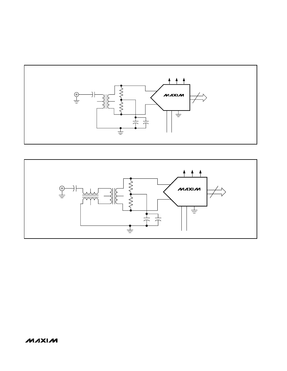
As stated previously, the signal inputs to the MAX1427
must be accurately balanced to achieve the best even-
order distortion performance. Figure 7 provides
improved balance over the circuit of Figure 6 by adding
a balun on the primary side of the transformer, and can
yield substantial improvement in even-order distortion
terms over the circuit of Figure 6.
One note of caution in relation to transformers is impor-
tant. Any DC current passed through the primary or
secondary windings of a transformer may magnetically
bias the transformer core. When this happens, the
transformer is no longer accurately balanced and a
degradation in the distortion of the MAX1427 may be
observed. The core must be demagnetized in order to
return to balanced operation.
MAX1427
56Ω
56Ω
0.1µF
0.1µF
0.01µF
T2-1T–KK81
15
D0–D14
AV
CC
DV
CC
DRV
CC
GND
CLKP
CLKN
INP
INN
SINGLE-ENDED
INPUT TERMINAL
Figure 6. Transformer-Coupled Analog Input Configuration
MAX1427
56Ω
56Ω
0.1µF
0.1µF
0.1µF
T2-1T–KK81
T2-1T–KK81
15
D0–D14
AV
CC
DV
CC
DRV
CC
GND
CLKP
CLKN
INP
INN
POSITIVE
TERMINAL
Figure 7. Transformer-Coupled Analog Input Configuration with Primary-Side Transformer