Electrical characteristics (continued) – Rainbow Electronics MAX1845 User Manual
Page 3
MAX1845
Dual, High-Efficiency, Step-Down
Controller with Accurate Current Limit
_______________________________________________________________________________________
3
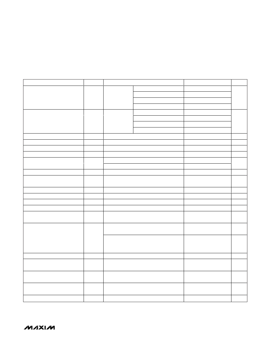
ELECTRICAL CHARACTERISTICS (continued)
(Circuit of Figure 1, V
DD
= V
CC
= 5V, SKIP = GND, V+ = 15V, T
A
= 0°C to +85°C, typical values are at +25°C, unless otherwise
noted.) (Note 1)
PARAMETER
SYMBOL
CONDITIONS
MIN
TYP
MAX
UNITS
TON = GND
160
182
204
TON = REF
205
234
263
TON = float
301
336
371
On-Time, Side 2 (Note 3)
t
ON2
V+ = 24V,
V
OUT2
= 2V
TON = V
CC
432
483
534
ns
TON = GND
125
135
145
TON = REF
125
135
145
TON = float
125
135
145
On-Time Tracking (Note 3)
On-time 2 with
respect to on-
time 1
TON = V
CC
125
135
145
%
Minimum Off-Time (Note 3)
t
OFF
400
500
ns
Quiescent Supply Current (V
CC
)
I
CC
FB_ forced above the regulation point
1100
1500
µA
Quiescent Supply Current (V
DD
)
I
DD
FB_ forced above the regulation point
<1
5
µA
Quiescent Supply Current (V+)
I+
Measured at V+
25
70
µA
ON1 = ON2 = GND, OVP = V
CC
or GND
<1
5
Shutdown Supply Current (V
CC
)
ON1 = ON2 = GND, V
OVP
= 1.8V
1
5
µA
Shutdown Supply Current (V
DD
)
ON1 = ON2 = GND
<1
5
µA
Shutdown Supply Current (V+)
ON1 = ON2 = GND, measured at V+,
V
CC
= GND or 5V
<1
5
µA
Reference Voltage
V
REF
V
CC
= 4.5V to 5.5V, no external REF load
1.98
2
2.02
V
Reference Load Regulation
I
REF
= 0 to 50µA
0.01
V
REF Sink Current
REF in regulation
10
µA
REF Fault Lockout Voltage
Falling edge, hysteresis = 40mV
1.6
V
Overvoltage Trip Threshold
(Fixed-Threshold Mode)
OVP = GND, with respect to error-
comparator trip threshold
112
114
117
%
1V < V
OVP
< 1.8V, external feedback,
measured at FB_ with respect to V
OVP
-28
0
28
mV
Overvoltage Comparator Offset
(Adjustable-Threshold Mode)
1V < V
OVP
< 1.8V, internal feedback,
measured at OUT_ with respect to OUT_
regulation point
-3.5
0
+3.5
%
OVP Input Leakage Current
1V < V
OVP
< 1.8V
-100
<1
100
nA
Overvoltage Fault Propagation
Delay
FB_ forced 2% above trip threshold
1.5
µs
Output Undervoltage Threshold
UVP = V
CC
, with respect to error-comparator
trip threshold
65
70
75
%
Output Undervoltage Protection
Blanking Time
From ON_ signal going high
10
30
ms
Current-Limit Threshold (Fixed)
GND - V
CS
, ILIM_ = V
CC
40
50
60
mV