Detailed description – Rainbow Electronics MAX1701 User Manual
Page 9
MAX1700/MAX1701
1-Cell to 3-Cell, High-Power (1A),
Low-Noise, Step-Up DC-DC Converters
_______________________________________________________________________________________
9
_______________Detailed Description
The MAX1700/MAX1701 are highly efficient, low-noise
power supplies for portable RF and data acquisition
instruments. The MAX1700 combines a boost switching
regulator, N-channel power MOSFET, P-channel syn-
chronous rectifier, precision reference, and shutdown
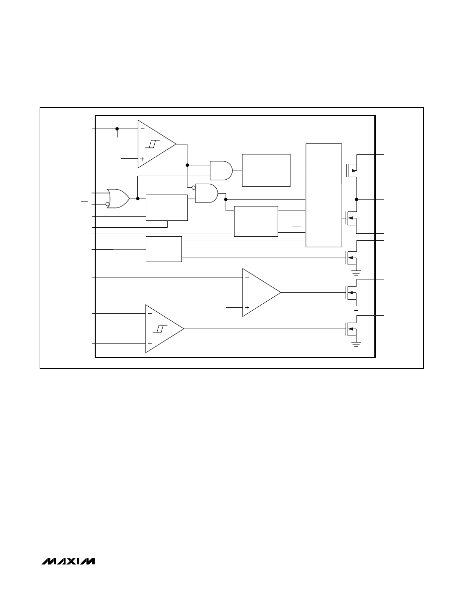
control. The MAX1701 contains all of the MAX1700 fea-
tures plus a versatile gain amplifier, POK output, and a
low-battery comparator (Figure 1). The MAX1700/
MAX1701 come in a 16-pin QSOP package, which
occupies no more space than an 8-pin SO.
The switching DC-DC converter boosts a 1- to 3-cell
input to an adjustable output between 2.5V and 5.5V.
The MAX1700/MAX1701 start from a low 1.1V input and
remain operational down to 0.7V.
These devices are optimized for use in cellular phones
and other applications requiring low noise during full-
power operation, as well as low-quiescent current for
maximum battery life during standby and shutdown
modes. They feature constant-frequency (300kHz), low-
noise PWM operation with up to 800mA output capabili-
ty. See Table 1 for typical available output current. A
low-quiescent-current, low-power mode offers an out-
put up to 100mA and reduces quiescent power con-
sumption to 200µW. In shutdown mode, the quiescent
current is further reduced to just 3µA. Figure 2 shows
the standard application circuit for the
MAX1700/MAX1701.
Additional features include synchronous rectification for
high efficiency and improved battery life, a POK output,
and an uncommitted comparator for low-battery detec-
tion (MAX1701). A CLK input allows frequency synchro-
nization to reduce interference. Dual shutdown controls
allow shutdown using a momentary pushbutton switch
and microprocessor control (MAX1701).
2.25V
IC PWR
1.25V
FEEDBACK AND
POWER-GOOD
SELECT
REFERENCE
UNDERVOLTAGE LOCKOUT
COMPARATOR
GAIN
BLOCK
FEEDBACK
START-UP
OSCILLATOR
OSCILLATOR
300kHz
PFM/PWM
CONTROLLER
PFM/PWM
PCH
0.25
Ω
NCH
0.13
Ω
REF
EN
D
EN
POUT
LX
PGND
POK*
AO*
LBO*
N
N
N
OSC
MODE
FB
EN
Q
Q
Q
*MAX1701 ONLY
LBP*
LBN*
ONA
REF
FB
GND
CLK/SEL
ON
RDY
REF
AIN*
ONB
OUT
Figure 1. Functional Diagram