Design procedure, Table 5. component selection guide, Table 4. component suppliers – Rainbow Electronics MAX1701 User Manual
Page 13
Reference
The MAX1700/MAX1701 have an internal 1.250V, 1%
bandgap reference. Connect a 0.22µF bypass capaci-
tor to GND within 0.2in. (5mm) of the REF pin. REF can
source up to 50µA of external load current.
Power-OK (MAX1701)
The MAX1701 features a power-good comparator. This
comparator’s open-drain output (POK) is pulled low
when the output voltage falls to 10% below the regula-
tion point.
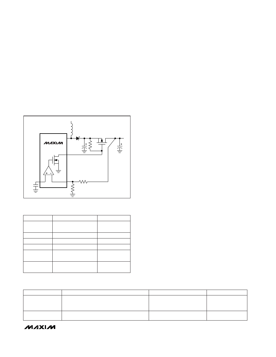
Gain Block (MAX1701)
The MAX1701’s gain block can function as a third com-
parator or can be used to build a linear regulator using
an external P-channel MOSFET pass device. The gain-
block output is a single-stage transconductance ampli-
fier that drives an open-drain N-channel MOSFET.
Figure 9 shows the gain block used in a linear regula-
tor. The output of an external P-channel pass element is
compared to the internal reference. The difference is
amplified and used to drive the gate of the pass ele-
ment. Use a logic-level PFET such as the Fairchild
NDS336P (R
DS(ON)
= 270m
Ω
). If the PFET R
DS(ON)
is
less than 250m
Ω
, the linear regulator output filter
capacitance may need to be increased to above 47µF.
__________________Design Procedure
Setting the Output Voltages
Set the output voltage between 2.5V and 5.5V by con-
necting a resistor voltage-divider to FB from OUT to
GND, as shown in Figure 2. The resistor values are then
as follows:
R1 = R2 (V
OUT
/V
FB
- 1)
where V
FB
, the boost-regulator feedback setpoint, is
1.23V. Since the input bias current into FB is less than
20nA, R2 can have a large value (such as 270k
Ω
or
less) without sacrificing accuracy. Connect the resistor
voltage-divider as close to the IC as possible, within
0.2in. (5mm) of the FB pin.
Inductor Selection
The MAX1700/MAX1701’s high switching frequency
allows the use of a small surface-mount inductor. A
10µH inductor should have a saturation-current rating
that exceeds the N-channel switch current limit of 1.6A.
However, it is generally acceptable to bias the inductor
current into saturation by as much as 20%, although
this will slightly reduce efficiency. For high efficiency,
choose an inductor with a high-frequency core material
(such as ferrite) to reduce core losses. To minimize
radiated noise, use a toroid, pot core, or shielded bob-
bin inductor. Connect the inductor from the battery to
the LX pin as close to the IC as possible. See Table 4
for a list of component suppliers and Table 5 for sug-
gested components.
MAX1700/MAX1701
1-Cell to 3-Cell, High-Power (1A),
Low-Noise, Step-Up DC-DC Converters
______________________________________________________________________________________
13
AIN
AO
N
LX
P
IN
REF
R6
R5
2x
100
µ
F
47
µ
F
MAX1701
20k
Figure 9. Using Gain Block as a Linear Regulator
PRODUCTION
INDUCTORS
CAPACITORS
DIODES
Surface Mount
Sumida CDR63B, CD73, CDR73B, CD74B series
Coilcraft DO1608, DO3308, DT3316 series
Matsuo 267 series
Sprague 595D series
AVX TPS series
Motorola MBR0520L
Through Hole
Sumida RCH654 series
Sanyo OS-CON series
Nichicon PL series
1N5817
Table 5. Component Selection Guide
(847) 956-0702
81-3-3607-5144
USA: (847) 956-0666
Japan: 81-3-3607-5111
Sumida
(619) 661-1055
81-7-2070-1174
USA: (619) 661-6835
Japan: 81-7-2070-6306
Sanyo
(602) 994-6430
USA: (602) 303-5454
Motorola
(714) 960-6492
USA: (714) 969-2491
Matsuo
(847) 639-1469
USA: (847) 639-6400
Coilcraft
(803) 626-3123
USA: (803) 946-0690
(800) 282-4975
AVX
FAX
PHONE
SUPPLIER
Table 4. Component Suppliers