Rainbow Electronics MAX1701 User Manual
Page 12
MAX1700/MAX1701
between the positive battery terminal and GND (Figure
5). The resistor values are then calculated as follows:
R3 = R4(V
TH
/V
LBN
-1)
where V
TH
is the desired input voltage trip threshold
and V
LBN
= V
REF
= 1.25V. Since the input bias current
into LBP is less than 20nA, R4 can be a large value
(such as 270k
Ω
or less) without sacrificing accuracy.
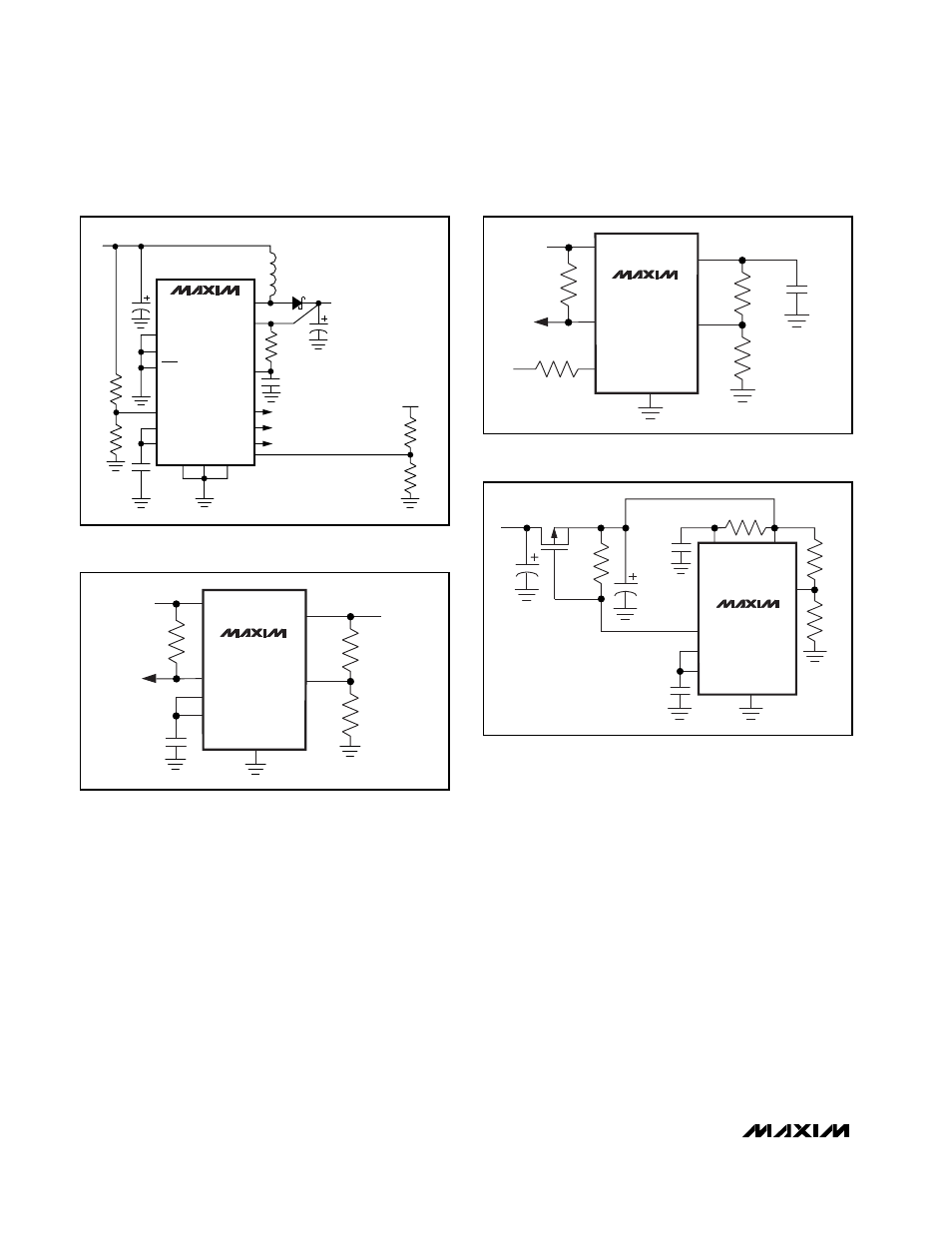
The inputs have a common-mode input range from
0.5V to 1.5V and an input-referred hysteresis of 15mV.
The low-battery comparator can also be used to moni-
tor the output voltage, as shown in Figure 6.
To set the low-battery threshold to a voltage below the
1.25V reference, insert a resistor divider between REF
and LBN and connect the battery to the LBP input
through a 10k
Ω
current-limiting resistor (Figure 7). The
equation for setting the resistors for the low-battery
threshold is then as follows:
R5 = R6(V
REF
/V
LBP
-1)
where V
LBP
is the desired voltage threshold. In Figures
5, 6, and 7, LBO goes low for a low-voltage input. The
low-battery comparator can be used to check the out-
put voltage or to control the load directly on P
OUT
dur-
ing start-up (Figure 8). Use the following equation to set
the resistor values:
R3 = R4(V
OUTTH
/V
LBP
- 1)
where V
OUTTH
is the desired output-voltage trip point
and V
LBP
is connected to the reference or 1.25V.
1-Cell to 3-Cell, High-Power (1A),
Low-Noise, Step-Up DC-DC Converters
12
______________________________________________________________________________________
FB
PGND
GND
AO
ARBITRARY VOLTAGE MONITOR
ARBITRARY
VOLTAGE
LOW-BATTERY MONITOR
VOLTAGE MONITOR
AIN
LBO
POK
OUT
POUT
LX
D1
L1
LBP
LBN
REF
CLK/SEL
ONA
ONB
R4
R6
R5
R3
10
Ω
0.22
µ
F
0.7V TO 5.5V
MAX1701
Figure 5. Detecting Battery Voltage Above 1.25V
MAX1701
LBN
LBO
LBP
POUT
REF
GND
R5
R6
BATTERY
VOLTAGE
10k
0.22
µ
F
MAX1701
LBO
REF
LBN
POUT
GND
R3
R4
0.22
µ
F
OUT
LBP
Figure 6. Using the Low-Battery Comparator to Sense the
Output Voltage (MAX1701)
Figure 7. Detecting Battery Voltages Below 1.25V (MAX1701)
270k
MAX1701
LBP
LBO
LBN
0.22
µ
F
OUT
POUT
10
Ω
REF
GND
R3
R4
P
C3
0.22
µ
F
C4
C5
OUTPUT
Figure 8. Using the Low-Battery Comparator for Load Control
During Start-Up