Applications information – Rainbow Electronics MAX1701 User Manual
Page 14
MAX1700/MAX1701
Output Diode
Use a Schottky diode, such as a 1N5817, MBR0520L, or
equivalent. The Schottky diode carries current during
start-up, and in PFM mode after the synchronous rectifier
turns off. Thus, its current rating only needs to be 500mA.
Connect the diode between LX and P
OUT
as close to the
IC as possible. Do not use ordinary rectifier diodes since
slow switching speeds and long reverse recovery times
will compromise efficiency and load regulation.
Input and Output Filter Capacitors
Choose input and output filter capacitors that will ser-
vice the input and output peak currents with accept-
able voltage ripple. Choose input capacitors with
working voltage ratings over the maximum input volt-
age, and output capacitors with working voltage ratings
higher than the output.
For full output, two 100µF, 100m
Ω
, low-ESR tantalum out-
put filter capacitors are recommended. For loads below
250mA, a single 100µF output capacitor will suffice. The
input filter capacitor (CIN) reduces peak currents drawn
from the input source and reduces input switching noise.
The input voltage source impedance determines the
required size of the input capacitor. When operating
directly from one or two NiCd cells placed close to the
MAX1700/MAX1701, use a 22µF, low-ESR input filter
capacitor. When operating from a power source placed
farther away, or from higher impedance batteries such as
alkaline or lithium cells, use one or two 100µF, 100m
Ω
,
low-ESR tantalum capacitors.
Sanyo OS-CON and Panasonic SP/CB-series ceramic
capacitors offer the lowest ESR. Low-ESR tantalum
capacitors are a good choice and generally offer a
good tradeoff between price and performance. Do not
exceed the ripple current ratings of tantalum capaci-
tors. Avoid most aluminum-electrolytic capacitors,
since their ESR is often too high.
Bypass Capacitors
Two ceramic bypass capacitors are required for proper
operation. Bypass REF with a 0.22µF capacitor to GND.
Also connect a 0.22µF ceramic capacitor from OUT to
GND. Each should be placed as close to their respec-
tive pins as possible, within 0.2in. (5mm) of the DC-DC
converter IC. See Table 4 for suggested suppliers.
__________Applications Information
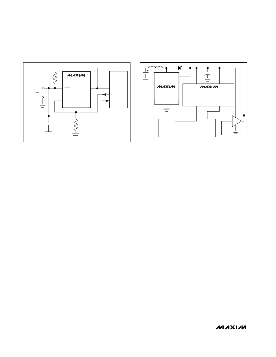
Push-On/Push-Off Control
A momentary pushbutton switch can be used to turn
the MAX1700/MAX1701 on and off. In Figure 10, ONA
is pulled low and ONB is pulled high when the part is
off. When the momentary switch is pressed, ONB is
pulled low and the regulator turns on. The switch must
be pressed long enough for the microcontroller to exit
reset (200ms) and drive ONA high. A small capacitor is
added to help debounce the switch. The controller
issues a logic high to ONA, which holds the part on
regardless of the switch state. To turn the regulator off,
press the switch again, allowing the controller to read
the switch status and pull ONA low. When the switch is
released, ONB is pulled high.
Use in a Typical Wireless
Phone Application
The MAX1700/MAX1701 are ideal for use in digital
cordless and PCS phones. The power amplifier (PA) is
connected directly to the boost-converter output for
maximum voltage swing (Figure 11). Low-dropout linear
regulators are used for post-regulation to generate
1-Cell to 3-Cell, High-Power (1A),
Low-Noise, Step-Up DC-DC Converters
14
______________________________________________________________________________________
µ
C
V
DD
I/O
MAX1701
ONA
ONB
OUT
I/O
0.1
µ
F
ON/OFF
270k
270k
Figure 10. Momentary Pushbutton On/Off Switch
MAX1700
POUT
LX
MAX8865/MAX8866 DUAL OR
MAX8863/MAX8864 SINGLE
LOW-DROPOUT LINEAR REGULATORS
RADIO
µ
C
PA
Figure 11. Typical Phone Application