Table 1. selecting output current levels – Rainbow Electronics MAX1641 User Manual
Page 8
MAX1640/MAX1641
The voltage at SET is given by:
R1 = R2 (V
REF
/ V
SET
-1 ); 10k
Ω
< R2 < 300k
Ω
where V
REF
= 2V and V
SET
is proportional to the
desired output current level.
The MAX1640/MAX1641 are specified for V
SET
between 0V and V
REF
. For V
SET
> V
REF
, output current
increases linearly (with reduced accuracy) until it
clamps at V
SET
≈
4V.
Pulse-Trickle Mode: Selecting the
Pulse-Trickle Current
Pulling D0 low and D1 high selects pulse-trickle mode.
This current equals V
SET
/ (13.3R
SENSE
) and remains
on for 12.5% of the period set by R
TOFF
. Pulse-trickle
current maintains full charge across the battery and
can slowly charge a cold battery before fast charging
commences.
Off Mode: Turning Off the Output Current
Pulling D0 and D1 low turns off the P-channel FET and
hence the output current flow. This mode also controls
end of charge and protects the battery against exces-
sive temperatures.
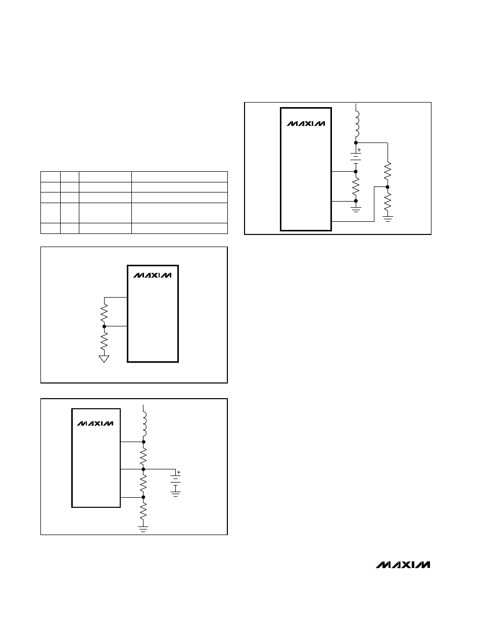
Setting the Maximum Output
Voltage Level
The maximum output voltage should be programmed to
a level higher than the output/battery voltage (I
LOAD
x
R
LOAD
). An external resistor-divider between the output
and ground (Figure 4) sets the voltage at TERM. Once
the voltage at TERM exceeds the reference, the internal
comparator turns off the P-channel FET, terminating
current flow. Select R4 in the 10k
Ω
to 500k
Ω
range.
R3 is given by:
R3 = R4 (V
OUT
/ V
TERM
) -1
PERIOD = 3.2 x 10 x R
(sec)
-7
TOFF
Adjustable-Output, Switch-Mode
Current Source with Synchronous Rectifier
8
_______________________________________________________________________________________
D1
DO
MODE
OUTPUT CURRENT (A)
0
0
OFF
0
0
1
Top-Off
V
SET
/ (13.3R
SENSE
)
1
0
Pulse-Trickle
V
SET
/ (13.3R
SENSE
)
12.5% duty cycle
1
1
Fast Charge
V
REF
/ (13.3R
SENSE
)
Table 1. Selecting Output Current Levels
MAX1640
MAX1641
REF
SET
R1
R2
Figure 3. Adjusting the Output Current Level
MAX1640
CS+
TERM
CS-
R3
R
SENSE
BATT
L
R4
Figure 4a. Setting the Maximum Output Voltage Level
MAX1641
CS+
TERM
CS-
R3
BATT
R4
R
SENSE
L
Figure 4b. Setting the Maximum Output Voltage Level