Applications information – Rainbow Electronics MAX1641 User Manual
Page 10
MAX1640/MAX1641
MAX1641’s high switching frequency demands a high-
speed rectifier (Table 2). Schottky diodes such as the
1N5817–1N5822 are recommended. Make sure the
Schottky diode’s average current rating exceeds the
peak current limit and that its breakdown voltage
exceeds the output voltage (V
OUT
). For high-tempera-
ture applications, Schottky diodes may be inadequate
due to their high leakage current; high-speed silicon
diodes such as the MUR105 or EC11FS1 can be used
instead. At heavy loads and high temperatures, the
benefits of a Schottky diode’s low forward voltage may
outweigh the disadvantage of high leakage current. If
the application uses an N-channel MOSFET synchro-
nous rectifier, a parallel Schottky diode is usually
unnecessary except with very high charge current (> 3
amps). Best efficiency is achieved with both an
N-channel MOSFET and a Schottky diode.
Inductor Value
Refer to the section
Programming the Off-Time
to select
the proper inductor value. There is a trade-off between
inductor value, off-time, output current ripple, and
switching frequency.
__________Applications Information
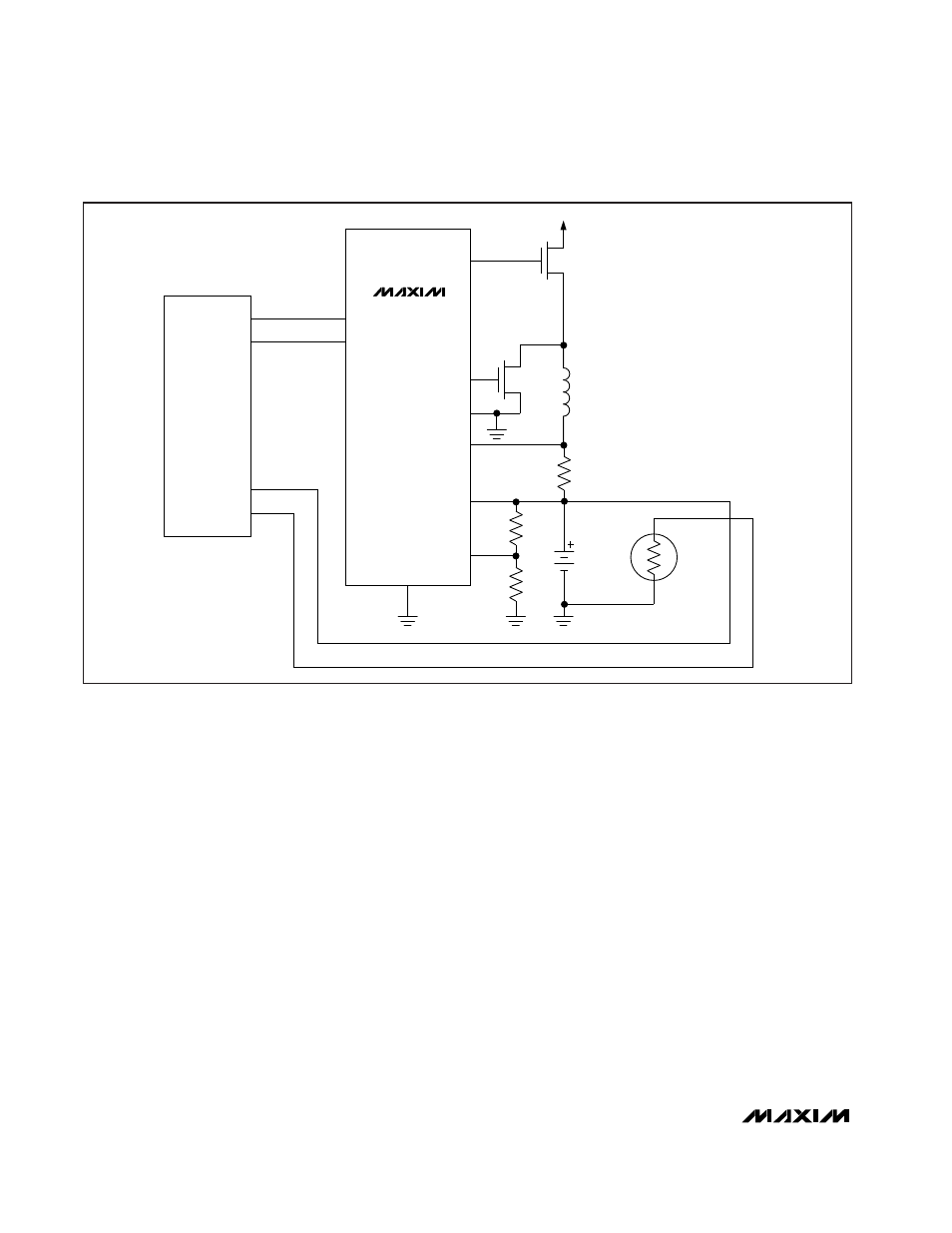
All-Purpose Microcontroller Battery
Charger: NiCd, NiMH
In applications where a microcontroller is available, the
MAX1640/MAX1641 can be used as a low-cost battery
charger (Figure 5). The controller takes over fast
charge, pulse-trickle charge, charge termination, and
other smart functions. By monitoring the output voltage
at V
OUT
, the controller initiates fast charge (set D0 and
D1 high), terminates fast charge and initiates top-off
(set D0 high and D1 low), enters trickle charge (set D0
low and D1 high), or shuts off and terminates current
flow (set D0 and D1 low).
Layout and Grounding
Due to high current levels and fast switching wave-
forms, proper PC board layout is essential. High-cur-
rent ground paths should be connected in a star
Adjustable-Output, Switch-Mode
Current Source with Synchronous Rectifier
10
______________________________________________________________________________________
P
N
D1
D0
T
I/0
I/0
CH1
CH0
PDRV
NDRV
PGND
CS+
CS-
R3
R4
TERM
GND
LOW-SIDE IS SHORTED
DC IN
R
SENSE
MAX1640
BATT
Figure 5. Microcontroller Battery Charger